H9 ASD Installation and Operation Manual 257
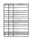
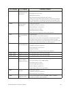
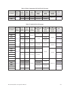
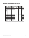
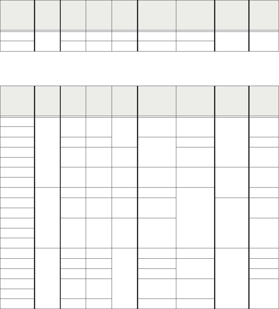
Table 17. 460-Volt H9 ASD Systems.
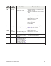
210K
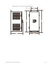
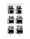
Figure 34
51.7/1313 14.6/371 17.6/447 50.2/1275 9.2/234
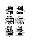
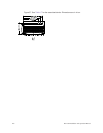
0.69/17.53 Figure 36-I
212K 53.1/1349 15.7/399 17.6/447 51.7/1313 9.9/252
Model Number
VT130H9U
Enclosure
Figure
Number
A
Height
(in/mm)
B
Width
(in/mm)
C
Depth
(in/mm)
D
Mounting Hole
Height
(in/mm)
E
Mounting Hole
Width
(in/mm)
R
Mounting Hole
Diameter
(in/mm)
Conduit
Plate
(Figure 35,
36, and 37)
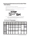
4055
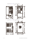
Figure 32
12.4/315 6.1/155
6.6/168
8.7/221 4.5/114
0.24/6.10
Figure 35-B
4080
4110 15.0/381 6.9/175
11.1/282
6.2/158 Figure 35-C
4160
15.1/384 8.3/211 7.6/193 7.5/191 Figure 35-D
4220
4270
19.3/490 9.1/231 7.6/193 15.2/386 8.3/211
0.24/6.10
Figure 35-E
4330
4400
Figure 33
25.9/658 11.1/282 13.2/335 25.0/635
8.0/203
Figure 35-F
4500
30.8/782 11.1/282 14.3/363 29.7/754
0.38/9.65
Figure 36-H
4600
4750
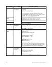
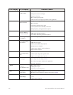
36.1/917 14.3/363 15.3/389 35.3/897 Figure 36-I410K
412K
415K
Figure 34
51.7/1313 14.6/371
17.6/447
50.2/1275 9.2/234
0.69/17.53
Figure 36-J
420K 53.1/1349 15.7/399 51.7/1313
9.9/252
Figure 36-K
425K 63.1/1603 15.0/381 61.6/1565 Figure 36-L
430K
68.5/1740 18.9/480 67.0/1701 13.8/351
Figure 37-M435K
440K 70.0/1778 25.6/650 68.5/1740 21.3/541
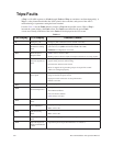
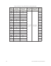
Table 16.Table Continuation 230-Volt H9 ASD Systems.
Model Number
VT130H9U
Enclosure
Figure
Number
A
Height
(in/mm)
B
Width
(in/mm)
C
Depth
(in/mm)
D
Mounting Hole
Height
(in/mm)
E
Mounting Hole
Width
(in/mm)
R
Mounting Hole
Diameter
(in/mm)
Conduit
Plate
(Figure 35,
36, and 37)


