


H9 ASD Installation and Operation Manual 17
Power Connection Requirements
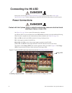
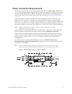
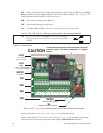
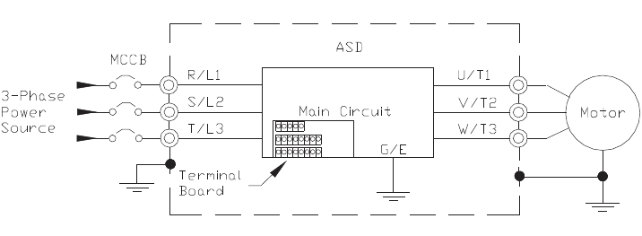
Connect the 3-phase input power to the input terminals of the H9 ASD at R/L1, S/L2, and T/L3 (see
Figure 3 for the typical electrical connection scheme). Connect the output of the ASD to the motor from
the ASD terminals U/T1, V/T2, and W/T3. The input and output conductors and terminal lugs used
shall be in accordance with the requirements listed in the section titled Current/Voltage Specifications
on pg. 263.
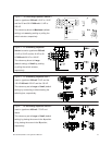
If multiple conductors are used in parallel for the input or output power and it is necessary to use
separate conduits, each parallel set shall have its own conduit and not share its conduit with other
parallel sets — i.e., place U1, V1, and W1 in one conduit and U2, V2, and W2 in another (refer to NEC
Article 300.20 and Article 310.4). National and local electrical codes should be referenced if three or
more power conductors are run in the same conduit (refer to 2005 NEC Article 310 adjustment factors).
Note: National and local codes should be referenced when running more than three
conductors in the same conduit.
Install a molded case circuit breaker (MCCB) or fuse between the 3-phase power source and the H9
ASD in accordance with the fault current setting of the H9 ASD and 2005 NEC Article 430.
The H9 ASD is designed and tested to comply with UL Standard 508C. Modifications to the ASD
system or failure to comply with the short circuit protection requirements outlined in this manual may
disqualify the UL rating. See Table 22 on pg. 267 for typeform-specific short circuit protection
recommendations.
As a minimum, the installation of the H9 ASD shall conform to 2005 NEC Article 110, the
Occupational Safety and Health Administration requirements, and to any other local and regional
industry codes and standards.
Note: In the event that the motor rotates in the wrong direction when powered up, reverse
any two of the three H9 ASD output power leads (U, V, or W) connected to the motor.
Figure 3. H9 ASD/Motor typical connection scheme.