


H9 ASD Installation and Operation Manual 23
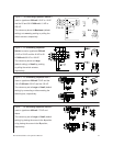
RX — The default function assigned to this terminal is the Torque Command setting. The RX terminal
accepts a ±10 VDC input signal that is used to carry out the function assigned to this terminal. This
input terminal may be programmed to raise or lower the speed or torque of the motor via an amplitude
setting or this terminal may be used to regulate the speed or torque of a motor by setting a limit. The
gain and bias of this terminal may be adjusted for application-specific suitability (see
F216 – F221). See
Figure 20 on pg. 26 for an electrical depiction of the RX terminal. This terminal references CCA.
V/I (I) — The function of the I input is to receive a 0 – 20 mA input signal that controls a 0 – 80 Hz
output. This is an isolated input terminal. This terminal is identified as V/I on the terminal board and
may be programmed to control the speed or torque of the motor. This terminal cannot be used when
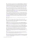
using the V input function. SW301 must be set to I to receive a current input signal at this terminal and
is the default setting from the factory (see
Figure 9 on pg. 24). This terminal references IICC. Scaling
of the V/I terminal is accomplished via F201 – F206. The gain and bias of this terminal may be adjusted
for application-specific suitability (see F470 and F471).
V/I (V) — The function of the V input terminal is to receive a 0 – 10 VDC input signal that controls a
0 – 80 Hz output. This is an isolated input terminal. This terminal is identified as V/I on the terminal
board and may be programmed to control the speed or torque of the motor. This terminal cannot be used
when using the I input. SW301 must be set to V to receive a voltage input signal at this terminal (see
Figure 9 on pg. 24). This terminal references IICC. Scaling of the V/I terminal is accomplished via
F201 – F206. The gain and bias of this terminal may be adjusted for application-specific suitability
(F470 and F471).
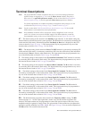
SU+ — Externally supplied +24 VDC ± 10% @ 1.1 A (minimum) backup control power. This terminal
references CC.
P24 — +24 VDC @ 200 mA power supply for customer use. This terminal references CCA.
PP — The function of output PP is to provide a 10 VDC/10 mADC output that may be divided using a
potentiometer. The tapped voltage is applied to the RR input to provide manual control of the RR
programmed function. This terminal references CCA.
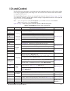
O1A/B (OUT1A/B) — The default function assigned to this terminal is Output Low Speed. This
output may be programmed to provide an indication (open or closed) that any 1 of the functions that are
listed in
Table 8 on pg. 241 has taken place. This function may be used to signal external equipment or
to activate the brake (see F130). The OUT1 terminal is rated at 2 A/120 VAC and 2 A/30 VDC.
O2A/B (OUT2A/B) — The default function assigned to this terminal is ACC/DEC Complete. This
output may be programmed to provide an indication (open or closed) that any 1 of the functions that are
listed in
Table 8 on pg. 241 has taken place. This function may be used to signal external equipment or
to activate the brake (see F131). The OUT2 terminal is rated at 2A/120 VAC and 2A/30 VDC.
FP — The default function of this output terminal is to output a series of pulses at a rate that is a
function of the output frequency of the ASD. As the output frequency of the ASD goes up so does the
FP output pulse rate. This terminal may be programmed to provide an output pulse rate that is
proportional to any one of the items listed in
Table 6 on pg. 239. For further information on this terminal
see F676 on pg. 196.
AM — This output terminal produces an output current that is proportional to the magnitude of the
function assigned to this terminal. The available assignments for this output terminal are listed in
Table
6 on pg. 239. For further information on this terminal see F670 on pg. 194.
FM — This output terminal produces an output current or voltage that is proportional to the magnitude
of the function assigned to this terminal. The available assignments for this output terminal are listed in
Table 6 on pg. 239. For further information on this terminal see F005 on pg. 78. The Voltage/Current
output selection is performed at F681.
SU+
P24
PP