


H9 ASD Installation and Operation Manual 81
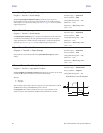
Upper Limit Frequency
Program ⇒ Fundamental ⇒ Frequency Settings
This parameter sets the highest frequency that the ASD will accept as a
frequency command or frequency setpoint. The ASD may output frequencies
higher than the Upper Limit Frequency (but, lower than the Maximum
Frequency) when operating in the PID Control mode, Torque Control mode,
or the Vector Control modes (sensorless or feedback).
Note: This setting may not be higher than the Maximum Frequency
(
F011) setting.
Direct Access Number — F012
Parameter Type — Numerical
Factory Default — (ASD-dependent)
Changeable During Run — Yes
Minimum — 0.0
Maximum — Max. Freq. (F011)
Units — Hz
Lower Limit Frequency
Program ⇒ Fundamental ⇒ Frequency Settings
This parameter sets the lowest frequency that the ASD will accept as a
frequency command or frequency setpoint. The ASD will output frequencies
lower than the Lower Limit Frequency when accelerating to the lower limit or
decelerating to a stop. Frequencies below the Lower Limit may also be output
when operating in the PID Control mode, Torque Control mode, or the
Vector Control modes (sensorless or feedback).
Direct Access Number — F013
Parameter Type — Numerical
Factory Default — 0.00
Changeable During Run — Yes
Minimum — 0.00
Maximum — Upper Limit (F012)
Units — Hz
Base Frequency 1
Program ⇒ Fundamental ⇒ Motor Set #1
The Base Frequency 1 setting is the frequency at which the output voltage of
the ASD reaches its maximum setting. The Base Frequency Voltage 1
parameter is set at
F409.
For proper motor operation, the Base Frequency should be set for the name-
plated frequency of the motor.
Direct Access Number — F014
Parameter Type — Numerical
Factory Default — 60.0
Changeable During Run — Yes
Minimum — 0.0
Maximum — Upper Limit (F012)
Units — Hz
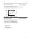
V/f Pattern
Program ⇒ Fundamental ⇒ Frequency Settings
This function establishes the relationship between the output frequency and the
output voltage.
Settings:
0 — Constant Torque
1 — Voltage Decrease Curve
2 — Automatic Torque Boost
3 — Sensorless Vector Control (speed)
4 — Sensorless Vector Control (Speed/Torque Switching)
5 — V/f 5-point Curve (Go to F190 to configure the V/f 5-point settings)
6 — PM Drive (Permanent Magnet)
7 — PG Feedback Vector Control (Speed)
8 — PG Feedback Vector Control (Speed/Torque Switching)
Note: When operating in the Vector Control mode the carrier
frequency should be set to 2.2
kHz or above.
The Automatic Torque Boost and the Sensorless Vector Control selections
use the motor tuning parameters of the drive to properly configure the ASD for
the motor being used. If Load Reactors or Long Lead Filters are used, or if
the capacity of the ASD is greater than the motor, manual tuning of the motor
parameters may be required for optimum performance.
Direct Access Number — F015
Parameter Type — Selection List
Factory Default — Constant Torque
Changeable During Run — No
F012 F015