


78 H9 ASD Installation and Operation Manual
FM Output Terminal Function
Program ⇒ Terminal ⇒ Analog Output Terminals
This parameter is used to set the output function of the FM analog output
terminal. The FM output terminal produces an output current or voltage that is
proportional to the magnitude of the function assigned to this terminal (select
current or voltage at
F681). The available assignments for this output terminal
are listed in Table 6 on pg. 239.
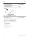
Note: To read voltage at this terminal connect a 100 – 500
Ω
resistor from
the FM (+) terminal to the CC (-) terminal. Using a voltmeter read
the voltage across the 100 – 500
Ω
resistor.
To read current at this terminal connect a 100 – 500
Ω
resistor from
the FM (+) terminal through a series Ammeter to the CC (-) terminal.
The FM analog output has a maximum resolution of 1/1024 and a
maximum load rating of 500 ohms.
FM Terminal Setup Parameters
F005 — Set FM Function
F006 — Calibrate FM Terminal
F681 — Voltage/Current Output Switching Selection
F682 — Output Response Polarity Selection
F683 — Set Zero Level
Direct Access Number — F005
Parameter Type — Selection List
Factory Default — DC (Bus) Voltage
Changeable During Run — Yes
FM Output Terminal Adjustment
Program ⇒ Terminal ⇒ Analog Output Terminals
This parameter is used to calibrate the FM analog output.
To calibrate the FM analog output, connect a meter (current or voltage) as
described at
F005.
With the drive running at a known value (e.g., output frequency), adjust this
parameter until the assigned function produces the desired DC level output at
the FM output terminal.
See F005 for more information on this setting.
Direct Access Number — F006
Parameter Type — Numerical
Factory Default — 493
Changeable During Run — Yes
Minimum — 1
Maximum — 1280
FM
F005 F006