


38 H9 ASD Installation and Operation Manual
Any or all of the Command and Frequency control input sources may be placed in the Override
mode.
Placing the H9 ASD in the Local mode (Local/Remote LED on) via the EOI places the RS485 (2-wire)
control selection in the Override mode for Command and Frequency input (see the section titled
Override Operation on pg. 38 for the proper setting). The Local/Remote control Override feature for
Command and Frequency (or either) may be enabled/disabled at Program ⇒ Utilities ⇒ Prohibition
⇒ Local/Remote Key (Command or Frequency) Override.
Communications may be used to place the remaining Command and eligible Frequency control input
sources in the Override mode. Once placed in the Override mode this setting is valid until it is
cancelled, the power supply is turned off, or the H9 ASD is reset.
Override Operation
The signal sources of Table 3 are scanned from left to right in the order that they are listed to determine
which input sources are in the Override mode (active Command or Frequency command present). The
first item detected as having the Override function turned on is the selection that is used for Command or
Frequency control input.
The Override control setting supersedes the setting of the Command mode setting (F003) and the
Frequency mode setting (F004). However, the F003 and F004 settings will be used in the event that the
register scan returns the condition that none of the listed items have the Override feature turned on or a
discrete input terminal is set to Serial/Local Switch and is activated.
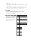
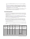
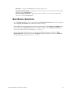
Command and Frequency-Control Override Hierarchy
Table 3 lists the input conditions and the resulting output control source selections for Command and
Frequency control Override operation.
The H9 ASD software reads the memory locations of the listed control sources from the left to the right.
The first item to be read that has the Override feature turned on will be used for Command or Frequency
control.
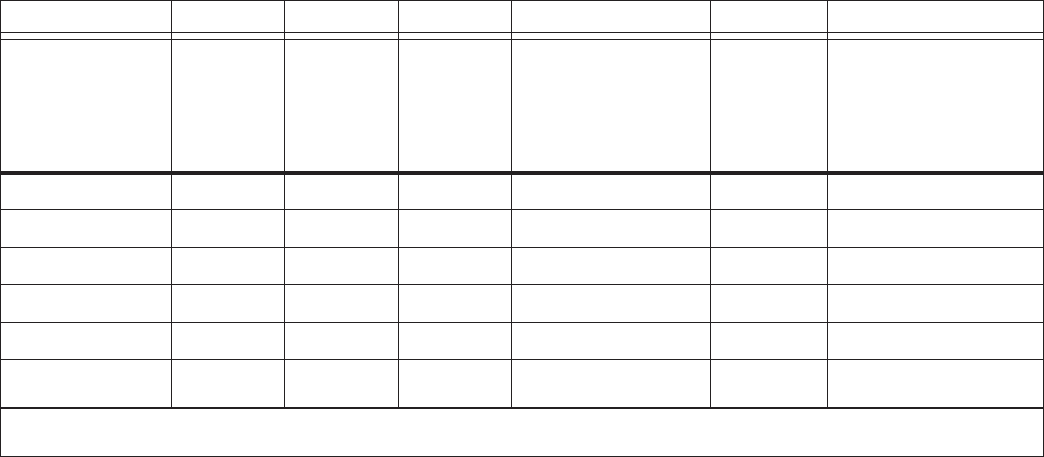
Table 3. Command and Frequency control hierarchy.
1 2 3 4 5 6 Priority Level
Forced F003/
F004 by I/P
Terminal
(assign to Serial/
Local Switch)
Comm.
Board
RS485
(4-wire)
RS485
(2-wire)
Terminal Board
(Binary/BCD Input)
F003/F004
Command/
Frequency Mode
1 X X X X X F003/F004 Setting
0 1 X X X X Communication Board
0 0 1 X X X RS485 (4-wire)
0 0 0 1 X X RS485 (2-wire)
0 0 0 0 1 X Terminal Board
0 0 0 0 0
F003/F004
Setting
F003/F004 Setting
Note: 1 = Override feature is turned on for that control input source; 0 = Override Off; X = Don’t Care.