


2-58
Cisco MGX 8230 Edge Concentrator Installation and Configuration
Release 1.1.31, Part Number 78-11215-03 Rev. B0, May 2001
Chapter2 Module and Service Descriptions
Frame Relay Service Modules
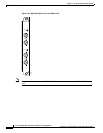
VISM Card Illustrations and LED Description
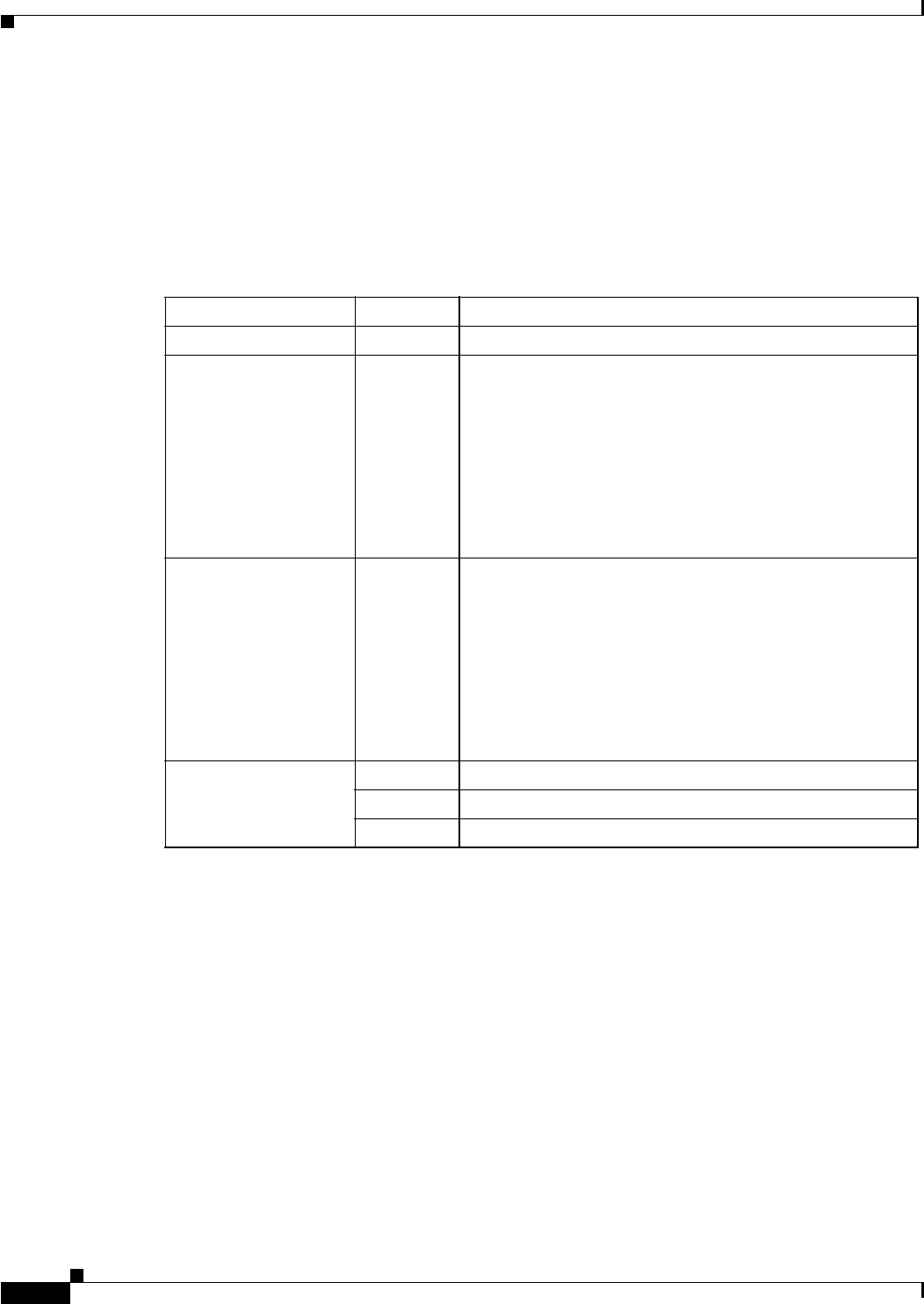
Table 2-15 is a description of the VISM card LED indicators.
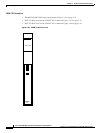
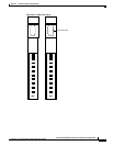
See Figure 2-29 for an illustration of the VISM Front Cards.
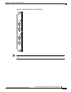
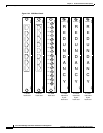
See Figure 2-30 for an illustration of the VISM Back Cards.
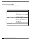
Table 2-15 LED Indicators for VISM
Type of LED Color Meaning
ACT LED (Active) Green On indicates the card set is in active mode.
STBY LED (Standby) Yellow
• Slow blink with the Active LED off indicates the card is
in the boot state.
• Fast blink with the Standby LED indicates the receiving
firmware.
• Fast blink indicates the service module is passing BRAM
channel information to the PXM1.
• Steady yellow indicates the card is in Standby mode and
the firmware is executing ADMIN code.
FAIL LED Red
• Steady red with Active and Standby LEDs off indicates
either the card is in the Reset condition, the card has
failed, or the card set is not complete (no line module).
• Steady red with Active LED on indicates the card was
active prior to failing.
• Steady red with Standby LED on indicates the card was
standby prior to failing.
• Both standby and red LED lit indicates self-test failure.
PORT LEDs Green Green indicates the port is active.
Red Red indicates a local alarm on the port.
Yellow Yellow indicates a remote alarm on the port.