


3-18
Cisco MGX 8230 Edge Concentrator Installation and Configuration
Release 1.1.31, Part Number 78-11215-03 Rev. B0, May 2001
Chapter3 Site Preparation
Power and Grounding
For DC supply connections, consult local or national codes for conductor sizing. Conductors must be
suitable for 30 Amps. Wiring that is 10 AWG (4 square millimeters) is adequate.
Bonding and Grounding
To maintain the full EMI and EMC integrity of this equipment, it must be bonded to an integrated ground
plane or an isolated ground plane network. The purpose of this requirement is to mitigate the damaging
effects to equipment from electrostatic discharge and lightning. Refer to the latest edition of ITU
Recommendation K.27 or Bellcore GR-1089-CORE requirements to ensure that the correct bonding and
grounding procedures are followed. As recommended in these documents, a frame bonding connection
is provided on the Cisco-supplied cabinet for rack-mounted systems.
Refer to the section “Making the Frame Bonding (Ground) Connection” in the IGX or the BPX
installation documents for information on how to make a connection.
Note Except for the AC power supply module, every module in a rack-mount system relies on the rack
itself for grounding. Therefore, the rack must be properly connected to protective earth before
operating the system.
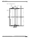
A DC-powered node must have grounding conductors that connect at two separate locations, as follows:
• The grounding conductor provided with the supply source must connect to the correct terminal of
the Power Entry Module (PEM).
• A grounding conductor as described previously must connect to the appropriate terminal of a rack
assembly or to the grounding point on the lower-right corner of the MGX 8230 chassis rear panel.
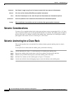
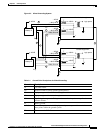
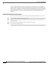
Wiring a Mixed Ground System with Redundant Supplies
A mixed ground system appears in Figure 3-3. This figure shows safety and earth grounds and the
primary and redundant DC sources Battery A and Battery B. Individual ground conductors are labeled
Z1, Z2, ..., Z5. The Z represents the impedance of the ground conductor between a chassis, for example,
and a connection to the building’s ground system. The numbers 1, ..., 4 represent building ground points
and indicate that an impedance can exist between different points in the ground system of the building.
Each of these symbols indicate that a voltage drop may result (but must not exceed 2 percent of the
referenced voltage). See Table 3-1 for a definition of each Z1–Z5.