


6-39
Cisco MGX 8230 Edge Concentrator Installation and Configuration
Release 1.1.31, Part Number 78-11215-03 Rev. B0, May 2001
Chapter6 Card and Service Configuration
Circuit Emulation Service Module for T3 and E3
• For E3
–
Cell delay of 2.9 msec
–
CDVT of 2 msec in increments of 125 microseconds
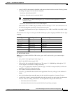
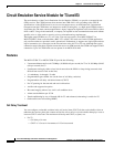
Error and Alarm Response
When it detects a loss of signal (LOS) alarm, the CESM notifies the connected CPE in the upstream
direction after an integration period. The CESM continues to emit cells at the nominal rate but sets the
ATM cell payload with an appropriate data pattern as specified by the ATM Forum CES V2.0
specification. Also, an OAM cell with RDI code goes to the far end to indicate out-of-service. The
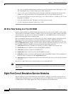
significance of the different types of alarms appears in Table 6-3.
Configuring Service on a T3 or E3 CESM
This section first describes the steps for configuring the card, line, and port-level parameters for an
MGX-CESM-T3 and MGX-CESM-E3. It then describes how to add a connection. If necessary, refer to
the section titled “Sequence of Configuration Tasks, page 6-2” for background information on these
types of tasks. Use either the CLI or the CiscoView application to set up the card and line parameters.
Use either the CLI or the Cisco WAN Manager application to add connections. The fundamental tasks
and applicable CLI commands appear in the following list. For a complete list of CLI commands that
apply to the CESM cards, use the Help command on the CLI of the card or refer to the tables at the front
of the Cisco MGX 8000 Series Command Reference.
• Optionally configure Y-cable redundancy at the card level (addred on the CLI).
• Optionally modify resource partitioning at the card level (cnfcdrscprtn)
• Activate a physical line (addln on the CLI) and optionally configure the line (cnfln) for line coding,
line length, and clock source
• Activate the functioning of the logical port on a physical line (addport)
• Optionally modify resource partitioning at the port level (cnfportrscprtn)
• Add the connections by using addcon (or addchan if NSAP addressing is necessary)
• Configure the connection for CDVT, cell loss integration period, and egress buffer size by using
cnfcon (or cnfchan if NSAP addressing is necessary)
Table 6-3 CESM Errors and Alarms
Error
Alarm
Typ e
Down
stream Up Stream Comments
Link Failure
(RX)
Blue (LOS) AIS—OAM
cells
none Data cells According to ATM-Forum
CES-IS V 2.0
Receive RAI Yellow None None
Receive LOF n/a n/a Not applicable
Receive AIS Blue (AIS) AIS (link) FERF OAM
cells
AIS—done over the T3/E3 link by
sending the AIS data over the T3/E3 link