


2-33
Cisco MGX 8230 Edge Concentrator Installation and Configuration
Release 1.1.31, Part Number 78-11215-03 Rev. B0, May 2001
Chapter 2 Module and Service Descriptions
Frame Relay Service Modules
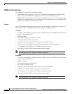
Card Combinations
The following card combinations are supported:
• MGX-FRSM-2CT3 front card with the BNC-2T3 back card
• MGX-FRSM-2T3E3 front card with a BNC-2T3 or BNC-2E3 back card
Note A special BNC-2E3A back card applies to Australia only. The BNC-2E3 applies to all other sites that
require E3 lines.
Illustrations
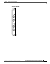
For Illustrations of the Very High Speed FRSM front and back cards, see the following illustrations:
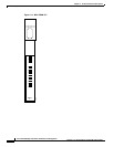
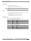
• For the MGX-FRSM-2CT3 front card, see Figure 2-16 on page 2-34.
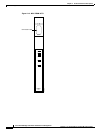
• For the MGX-FRSM-2T3E3 front card, see Figure 2-17 on page 2-35.
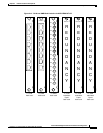
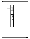
• For the MGX-BNC-2T3 back card, see Figure 2-18 on page 2-36.
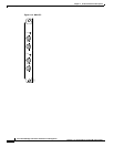
• For the MGX-BNC-2E3 back card, see Figure 2-19 on page 2-37.
FRSM-2T3E3 LED Indicators
Table 2-6 and Table 2-7 describe the FRSM-2T3E3 LED faceplate indicators.
Table 2-6 Card Level LED Indicators for the FRSM-2T3E3
Type of LED Color Meaning
ACT LED Green Active
STBY LED Yellow Standby
FAIL LED Red Fail
Table 2-7 Line Level LED Indicators for the FRSM-2T3E3
Type of LED Color Meaning
Individual Port LEDs Green Active and OK
Red Active and Local Alarm
Yellow Active and Remote Alarm