


4-16
Cisco MGX 8230 Edge Concentrator Installation and Configuration
Release 1.1.31, Part Number 78-11215-03 Rev. B0, May 2001
Chapter4 Enclosure Installation
Rack Mounting an MGX 8230
Step 3 Make sure that the building AC receptacle is properly grounded.
Step 4 Repeat steps 2 through 3 for the second AC Power Supply Module if appropriate.
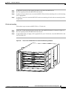
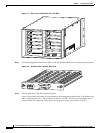
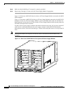
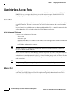
Figure 4-12 illustrates a MGX 8230 chassis with two AC Power Supply Modules connected to the MGX
8230 backplane.
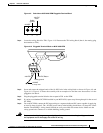
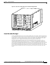
Figure 4-13 illustrates an MGX 8230 with one AC Power Supply Module connected to the MGX 8230
backplane. If only one AC Power Supply Module is used in your MGX 8230, make sure that there are
blank faceplates covering the slots for the second AC Power Supply Module and the opening where the
DC PEM would otherwise be installed.
In order for the AC power supply to function the enable switch must be in the “On” position, and the DC
cable must be connected between the AC power supply connector and the MGX 8230 backplane.
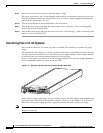
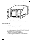
Proceed to the section “Install the Cable Manager,” which is followed by the section “Power up the MGX
8230.”
Note An AC power module will not power on if the DC cable is disconnected from the MGX 8230
backplane.
Figure 4-12 Rear View of MGX 8230 with Two Optional AC Power Supply Modules
A
C
D
C
A
C
D
C
23825