


2-28
Cisco MGX 8230 Edge Concentrator Installation and Configuration
Release 1.1.31, Part Number 78-11215-03 Rev. B0, May 2001
Chapter2 Module and Service Descriptions
Frame Relay Service Modules
• Each interface configurable as a single port (FRSM-8T1) or up to 24 ports (FRSM-8T1-C) running
at full line rate, at 56 or n x 64 kbps
• Bit error rate tester (BERT) and extended loopback pattern generation/verification (with optional
SRM)
• 1:N redundancy within a group of n + 1 FRSM cards on a shelf (with optional SRM)
• LOS, OOF, AIS, RAI alarms
• Transmitter loop-timed to receiver or synchronized to shelf
• Supports up to 1000 virtual connections per card
FRSM for E1 features
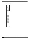
The FRSM-8E1 and FRSM-8E1-C each provide eight E1 interfaces for full-duplex communications at
up to 2.044 Mbps. Each E1 line consists of an RJ-48 and SMB mini-connector, along with three LED
indicators for line status.
The FRSM-8E1 supports fractional and unchannelized E1 port selection on a per-E1 basis. The
FRSM-8E1-C allows full DS0 and n x DS0 channelization of the E1s, for a maximum of 248 ports per
FRSM-8E1-C.
Key Features include:
• Eight E1 (2.048 Mbps +/-50 bps or 32 ppm) lines
• HDB3 or AMI line coding
• ITU G.704 16-frame multiframe line framing and clear channel E1
• Each interface configurable as a single port (FRSM-8E1) or up to 31 ports (FRSM-8E1-C) running
at full line rate, at 56 or n x 64 kbps
• BERT and extended loopback pattern generation/verification (with optional SRM)
• 1:N redundancy within a group of n + 1 FRSM cards on a shelf (with optional SRM)
• LOS, OOF, AIS, RAI alarms
• Transmitter loop-timed to receiver or synchronized to shelf
• Supports up to 1000 virtual connections per card
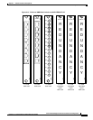
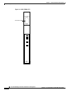
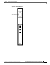
LED Indicators
Table 2-4 and Table 2-5 describe the FRSM T1/E1 LED faceplate indicators.
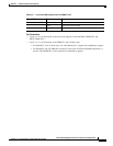
Table 2-4 Card Level LED Indicators for the FRSM T1/E1
Type of LED Color Meaning
ACT LED Green Active
STBY LED Yellow Standby
FAIL LED Red Fail