


1-5
Cisco MGX 8230 Edge Concentrator Installation and Configuration
Release 1.1.31, Part Number 78-11215-03 Rev. B0, May 2001
Chapter 1 Introducing the MGX 8230
MGX 8230 System Overview
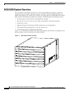
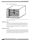
• Each service module slot can accept one single-height card or be converted to accept two
double-height cards.
• Slots are 1 and 2 are always double-height slots and reserved for the primary and redundant MGX
8230 Processor Switch Modules (PXM1s).
• Slots 7 and 14 are reserved for SRM modules only: no other service modules can be used in these
two slots.
• Eight single-height slots (four double-height slots) are available for service modules.
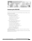
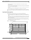
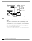
Figure 1-2 is a conceptual drawing of an MGX 8230 showing the dimensions and the slot numbering.
The slot numbering is as it appears from the front of the MGX 8230; slots 8 and 9 refer to back card slots
only.
Single Height and Double Height Slots
Single-height slots on the MGX 8230 chassis can be converted into double-height slots.
• When a double-height front card is plugged in, the left slot number is used. The back cards are
numbered according to the front card numbering scheme, with the exception of slots 8 and 9 as noted
below.
• Since front slots 1 and 2 are always double-height for PXM1 processor modules, slots 8 and 9 only
refer to the back card slots that correspond to the two lower single-height slots on the left side of the
chassis as seen from the rear.
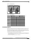
• When converting single-height slots into double-height slots the conversion must start from the
bottom and be contiguous. For example, before you can convert slot 4 into double height, slot 3 must
be converted first (as shown in Figure 1-3 on page 1-6).
Figure 1-2 MGX 8230 Slot Placement
SRM
7
6
5
4
3
2
1
SRM
SM SM
SM SM
SM SM
SM
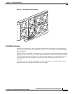
F
A
N
T
R
A
Y
7 RU
(12.25 in.,
31.1 cm.)
17.72 in.
(45 cm.)
1 RU
(1.75 in.,
4.5 cm.)
PXM 2
PXM 1
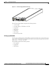
Optional AC power tray
14
13
12
11
10
23.5 in.,
(59.7 cm.)
38375
8
9