


B-3
Cisco MGX 8230 Edge Concentrator Installation and Configuration
Release 1.1.31, Part Number 78-11215-03 Rev. B0, May 2001
AppendixB Cable Specifications
Frame Relay Cabling
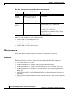
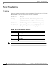
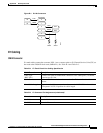
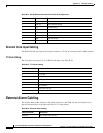
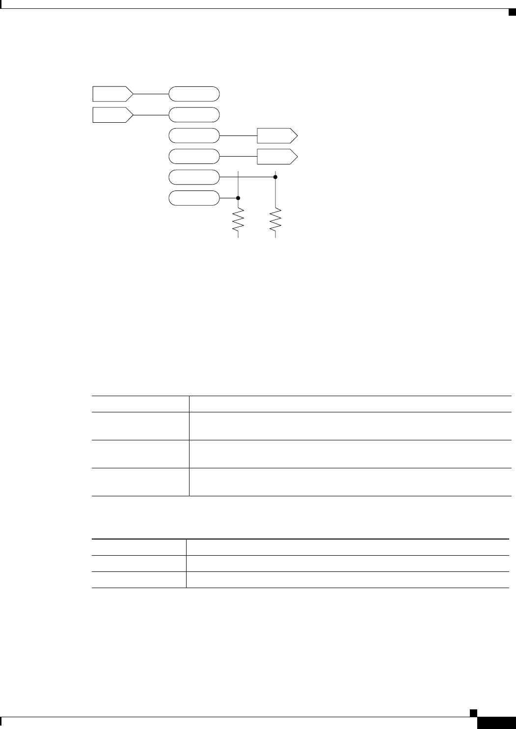
Figure B-1 RJ-48 Connectors
E1 Cabling
SMB Connector
E1 trunk cables connect the customer DSX-1 cross-connect point or E1 Channel Service Unit (CSU) to
the node at the FRSM E1 back card (SMB-8E1). See Table B-4 and Table B-5.
TTIP
TRNG
RJ-48 Pins
RRNG
RTIP
shield
shield
2
1
5
4
3
6
IN
IN
OUT
OUT
26270
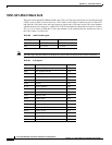
Table B-4 E1 Trunk/Circuit Line Cabling Specification
Cable Parameter Description
Cable Type
(BNC-8E1)
75-ohm coax cable for unbalanced connection. Two cables/pairs (1 transmit,
1 receive) per E1 line.
Cable Connector 16 female SMB for unbalanced connection. See Tables A-2 and A-4 for
pinouts.
Max. Cable Length Approximately 100 meters maximum between the MGX 8230 node and the
first repeater or CSU. Equalizer for cable length.
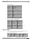
Table B-5 E1 Connector Pin Assignments (unbalanced)
Connector Description
Rx BNC Receive E1 from trunk
Tx BNC Transmit E1 to trunk