


CHAPTER
2-1
Cisco MGX 8230 Edge Concentrator Installation and Configuration
Release 1.1.31, Part Number 78-11215-03 Rev. B0, May 2001
2
Module and Service Descriptions
This chapter includes detailed descriptions of the modules, cards and services available with the
MGX 8230:
• Processor Switching Module, page 2-1.
• Service Resource Module, page 2-12.
• ATM UNI Service Module (AUSM), page 2-15.
• Frame Relay Service Modules, page 2-20.
• Circuit Emulation Service Modules, page 2-45.
• Voice Service: The VISM, page 2-55.
Note Although the illustrations in this chapter display the equipment in a vertical position, the cards and
modules are rotated 90 degrees (to a horizontal position) when installed in the MGX 8230 back card
slots. See the “MGX 8230 Enclosure and Power” section on page 1-4 for more information on slot
assignments and module installation.
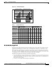
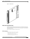
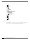
Processor Switching Module
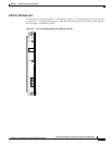
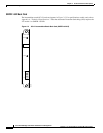
The PXM1 card set consists of the PXM1 front card, the PXM1 User Interface back card (PXM1-UI or
PXM-UI-S3), and various uplink back cards that can serve as either a trunk or a UNI.
For physical details of PXM1 cards, see Appendix A, “Technical Specifications.”
Caution Handle the PXM1 front card very carefully to preserve the alignment of the attached disk drive. Do
not drop or bump the PXM1.
Caution Before using the 8230, verify that the daughter card on the PXM1 corresponds to the uplink card type.
Serious damage may result if the power is on and these cards are mismatched.
Note The PXM1 processor module for the MGX 8230 is identical to the PXM1 for the MGX 8250.