


A-9
Cisco MGX 8230 Edge Concentrator Installation and Configuration
Release 1.1.31, Part Number 78-11215-03 Rev. B0, May 2001
Appendix A Technical Specifications
FRSM-2CT3 Specifications
FRSM-2CT3 Specifications
This section provides details for the FRSM-2CT3. Topics consist of the following:
• Transport technology standards with which the card complies (Table A-8)
• General physical attributes of the card, such as LEDs on the faceplate (Table A-9)
• Line and framer characteristics (Table A-10 and “FRSM-2CT3 Framer” section)
• Line alarms (“FRSM-2CT3 Line Alarms”)
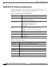
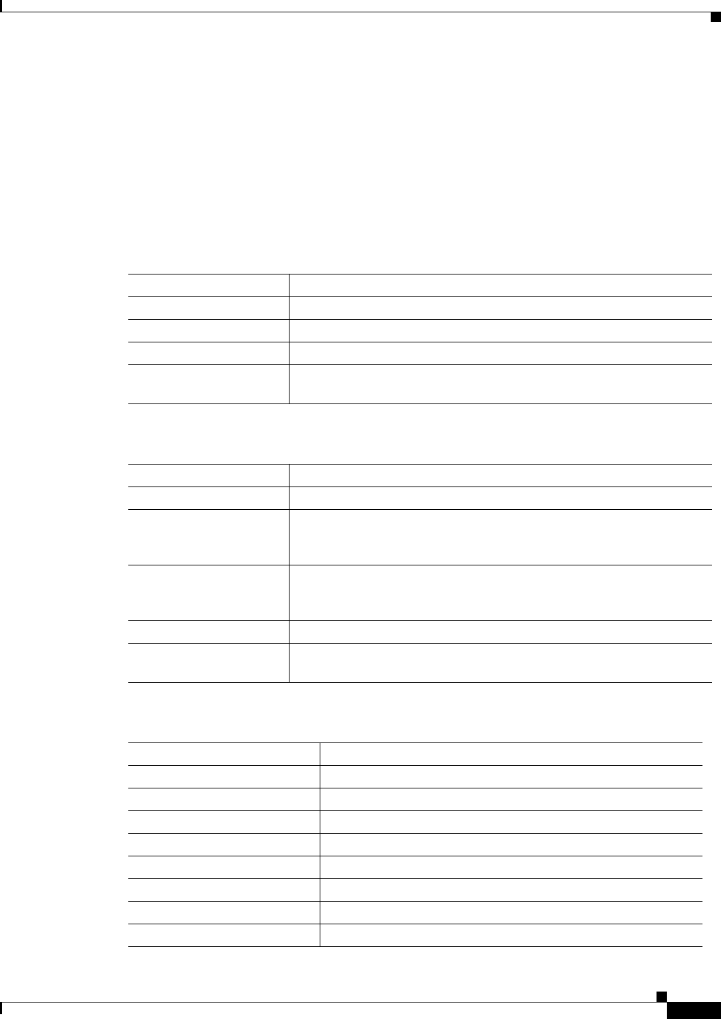
Table A-8 Frame Relay Interface Standards
Interface Standard
Frame Relay Interface ANSI T1.618, 2-octet header
ATM Layer CCITT I.361 and ATM UNI v3.1
AAL Layer AAL5 per ITU-T I.363
FR-Cell Interworking Per ITU-T I.555 and I.36x.1, as summarized in “ATM-to-Frame Relay
Interoperability Implementation Agreement” v 1.0
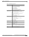
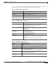
Table A-9 FRSM-2CT3 Front Card Physical Characteristics
Feature Significance or Value
Power –48 VDC, 60W (estimated)
Card Status Indicator
LEDs
Active (Green),
Failed (Red),
Standby (Yellow)
Line Status Indicator
LEDs
Active & Okay (Green),
Active & Local Alarm (Red),
Active & Remote Alarm (Yellow)
Reliability > 85000 hours MTBF (target)
Card Size Front card: 7.25 inches by 15.83 inches (18.42 cm by
42.75 cm)
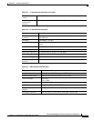
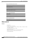
Table A-10 FRSM-2CT3 Line Level
Feature Significance or Value
Number of T3 Lines Two
Line Interface Connector 75 ohm BNC
Line Rate 44.736 Mbps +/- 20 ppm
Line Coding B3ZS
Transmit Timing Normal or Loop timed
Input Jitter Tolerance Per GR-449-CORE, ITU-T G.824
Output Jitter 0.05 UI maximum with jitter-free input clock
Output Pulse Per T1.102.1993