


2-4
Cisco MGX 8230 Edge Concentrator Installation and Configuration
Release 1.1.31, Part Number 78-11215-03 Rev. B0, May 2001
Chapter2 Module and Service Descriptions
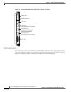
Processor Switching Module
• Maintenance, Control and LAN ports.
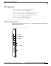
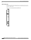
PXM-UI-S3 (optional)
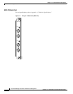
The PXM-UI-S3 back card shown in Figure 2-3 provides Stratum 3 clocking:
• One RJ-45/48 connector for external T1 or E1 clock input (CLK1).
• One DB-15 female connector for alarm interface (Alarm)
• Maintenance, Control and LAN ports.
Note The LAN2 and CLK2 ports on the PXM-UI-S3 are not supported in this release. All external
connections are made with the LAN1 and CLK1 ports.
Making External Clock Connections
If external equipment or a local digital central office is to provide synchronization, the external clock
source is connected to the PXM1-UI or PXM-UI-S3 back card.
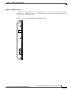
Stratum 4 clocking
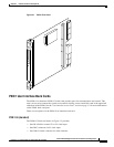
External clocking sources are connected to the PXM1-UI back card (Figure 2-2).
• One RJ-45/48 connector for external T1 or E1 clock input.
• One BNC connector for E1 clock input.
Stratum 3 clocking
External clocking sources are connected to the PXM-UI-S3 back card (Figure 2-3).
• For T1 and E1 Stratum 3 external clock input, connect the source to the RJ-45/48 connector labeled
“CLK1.”
Note The LAN2 and CLK2 ports on the PXM-UI-S3 are NOT supported in this release. All external
connections are made with the LAN1 and CLK1 ports.
See Chapter 5, “Configuring the MGX 8230 Shelf” for further information on configuring an external
clocking source.