


1-9
Cisco MGX 8230 Edge Concentrator Installation and Configuration
Release 1.1.31, Part Number 78-11215-03 Rev. B0, May 2001
Chapter 1 Introducing the MGX 8230
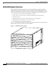
MGX 8230 System Overview
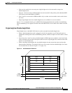
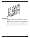
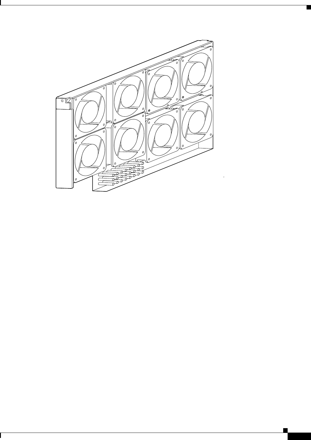
Figure 1-6 MGX 8230 Fan Tray Assembly
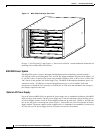
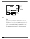
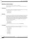
MGX 8230 Architecture
The MGX 8230 architecture is built around the switching fabric on the processor switching module
(PXM1), the backplane, and the service modules. Figure 1-7 is a very simple block diagram of the MGX
8230 architecture.
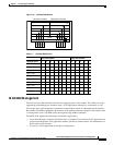
The main functions of the MGX 8230 backplane are to connect cards together, terminate critical signals
properly, provide -48 VDC power to all cards, and set ID numbers for each slot. In addition, the MGX
8230 backplane interconnects both front cards and back cards together via pass-through connectors. A
software readable ID on the backplane is available for software to identify that the chassis is an
MGX 8230.
The cell bus controllers (CBCs) are application-specific integrated circuits (ASICs) and provide the
interface between the switching fabric and the service modules.
17274