


2-29
Cisco MGX 8230 Edge Concentrator Installation and Configuration
Release 1.1.31, Part Number 78-11215-03 Rev. B0, May 2001
Chapter 2 Module and Service Descriptions
Frame Relay Service Modules
Card Illustrations
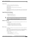
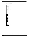
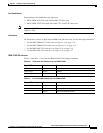
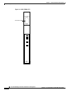
• Figure 2-14 is an illustration of the front card (applies to both the MGX-FRSM-8T1 and
MGX-FRSM-8E1).
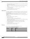
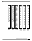
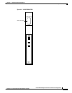
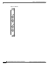
• Figure 2-15 is an illustration of the FRSM T1 and E1 back cards.
–
AX-RJ48-8T1 is the T1 back card. An AX-R-RJ48-8T1 is required for redundancy support.
–
AX-RJ48-8E1 and AX-SMB-8E1 are the E1 back cards for RJ48 and SMB connections. A
special AX-R-SMB-8E1 card is required for redundancy support.
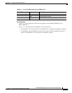
Table 2-5 Line Level LED Indicators for the FRSM T1/E1
Type of LED Color Meaning
Individual Port LEDs Green Active and OK
Red Active and Local Alarm
Yellow Active and Remote Alarm