


A-4
Cisco MGX 8230 Edge Concentrator Installation and Configuration
Release 1.1.31, Part Number 78-11215-03 Rev. B0, May 2001
Appendix A Technical Specifications
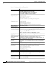
MGX 8230 Processor Switching Module Specifications
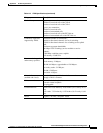
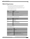
LEDs on PXM front
card:
LEDs display status, but
alarm history is a switch.
Status for the card:
• Green means active.
• Red means failed.
• Yellow indicates the standby card.
LAN activity: flashing green indicates activity.
Node alarm:
• Red indicates major alarm.
• Yellow indicates minor alarm.
Node power (note that each AC power supply also has an
LED):
• “DC OK A” is green for okay or red for trouble.
• “DC OK B” is green for okay or red for trouble.
Alarm history: ACO
Port interface (per port):
• Green means active and okay.
• Red means active and local alarm.
• Yellow means active and remote alarm.
• No light means inactive or not provided.
LEDs on back cards: Green means active. No light means inactive or not provided.
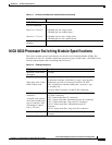
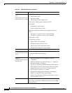
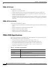
Stratum 4
synchronization (internal
only):
8 KHz clock derived from:
• Internal 8 KHz clock (10 ppm).
Stratum 3
synchronization (internal
and external):
• Free-Run Accuracy of +/- 4.6 ppm (+/- 7 Hz @
1.544 MHz)
• Holdover stability of less than 255 slips (+/- .37 ppm ) for
the initial 24 hours of holdover.
• Upon clock switchover, MTIE (Maximum Time Interval
Error) shall not exceed 1 microsecond. The rate of phase
change shall not exceed 81 ns in 1.326 ms interval.
• Pull-in range of accuracy +/- 4.6 ppm.
• Provide jitter filtering and tolerate jitter according to
AT&T T1.5 and ITU G.824 specifications.
• Declare a bad reference if LOS detected >50 ms or error
burst of duration >2.5 sec.
BITS clock interface: T1 and E1 with an RJ-45 connector.
Note: older systems with a PXM-UI back card have an SMB
connector for E1.
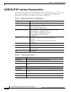
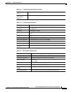
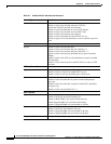
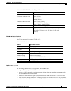
Table A-2 PXM Specifications (continued)
Category Description