


4-7
Cisco MGX 8230 Edge Concentrator Installation and Configuration
Release 1.1.31, Part Number 78-11215-03 Rev. B0, May 2001
Chapter 4 Enclosure Installation
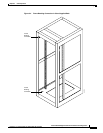
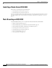
Rack Mounting an MGX 8230
Install the MGX 8230 Without a Mechanical Lift (Optional)
Because of the risk of damage to the modules and backplanes, Cisco strongly recommends the use of a
mechanical lift. Using a lift greatly simplifies the installation and reduces the risk of damage. See Install
the MGX 8230 Using a Mechanical Lift (Recommended), page 4-6.
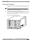
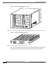
If a mechanical lift is not available for installation, the MGX 8230 must be manually lifted into place.
Since the MGX 8230 is shipped with all equipment pre-installed, you may have to remove some of the
service modules, the AC Power Supply Modules, or the Fan Tray Assembly to more easily lift the chassis
into the rack.
This section contains instructions to install a MGX 8230 chassis without the use of a mechanical lift.
Prepare for Installation
Review the following points before installation is begun:
• Handle the PXM front card very carefully. This card contains a disk drive that is easily damaged.
Cisco recommends not removing the PXMs.
• Before removing any modules or assemblies, Cisco suggests that you carefully note and write down
their location or slot number in the chassis.
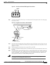
• The MGX 8230 includes a grounding wrist strap to protect the user and the electronic components
from electrostatic shock. This strap can be connected to the lower rear corner near the grounding
lug, or to the front panel.
• Inserting the cards in the correct slot. If back cards are installed in the wrong slot, electrical damage
may occur. If a back card is inserted into a PXM back slot (1 or 2), damage to the card and backplane
can result. Never remove or insert either card in a PXM/SONET back card set with the power on.
• If a service module back card is accidently inserted into slots 1 or 2 and then removed, check for
bent or broken pins on the backplane. Such damage can result in faulty operation of the switch.
• Both the front card and the corresponding back card of all card sets must be installed for proper
operation.
• If a back card is removed, reseated or changed for another back card, the associated front card must
be reset.
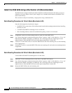
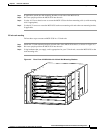
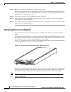
Remove the Front Cards
The front cards are held in place by a mechanical latch attached to the card. The top of a front card
corresponds to the left side of the MGX 8230 card cage as seen from the front, as shown in Figure 4-4.
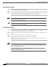
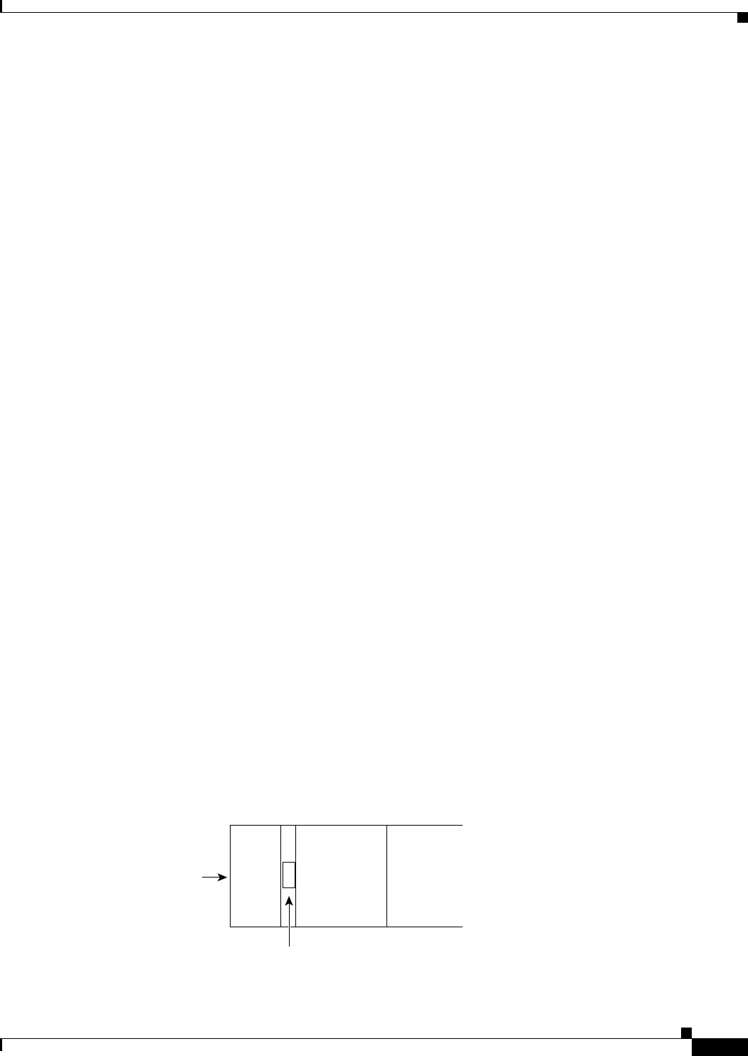
Figure 4-4 Front Card Insertion/Extractor Lever
To remove a front card:
• • • • •
Left side or
top of card
Slot
26267