


2-13
Cisco MGX 8230 Edge Concentrator Installation and Configuration
Release 1.1.31, Part Number 78-11215-03 Rev. B0, May 2001
Chapter 2 Module and Service Descriptions
Service Resource Module
Module Requirements with Bulk Distribution and Redundancy
The use of bulk distribution affects the requirements for SRM and service module back cards:
• With bulk distribution and 1:N redundancy support by way of the distribution bus, the service
modules do not use back cards.
• For just 1:N redundancy by way of the redundancy bus, the supported service modules must have
back cards—including one special redundancy back card. E1 redundancy requires the
AX-R-RJ48-8E or AX-R-SMB-8E1 line module, and T1 redundancy requires the R-RJ48-8T1 line
module.
• For bulk distribution, the T3 lines connect to an external multiplexer. The T1 lines on the other side
of the multiplexer connect to the CPE. The SRM converts the received traffic from its T3 lines to T1
channels and sends the data to linked service modules. For instructions on linking T1 channels and
card slots to the MGX-SRM-3T3/C, see Chapter 6, “Card and Service Configuration”
Installation Requirements for the MGX-SRM-3T3/C
The following are card-level characteristics that apply to any SRM installation:
• Only MGX-SRM-3T3/C cards can be installed in slots 7 and 14.
• No other service modules can be installed in slots 7 and 14. These slots do not have cell bus
connections. The SRM modules use a local bus to communicate with the PXM.
• The PXM1 in slot 1 controls the SRM in slot 7. The PXM1 in slot 2 controlsthe SRM in slot 14.
• Either SRM in slot 7 or 14 can be active (depending on the active PXM1).
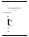
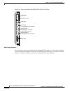
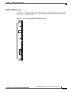
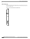
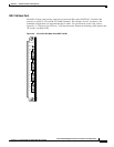
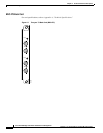
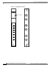
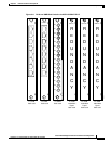
SRM Illustration and LED Indicators
Table 2-1 and Table 2-2 describe the SRM-3T3 LED faceplate indicators.
Table 2-1 LED Indicators for the SRM-3T3/C
Type of LED Color Meaning
ACTIVE (ACT) LED Green Indicates card set is in active mode.
STANDBY (STBY)
LED
Yellow Indicates card set is in standby mode.
FAIL (FAIL) LED Red Indicates BNM-155 card set has failed or the line
module is missing.
Table 2-2 Line Redundancy LED Indicators for the SRM-3T3/C
Type of LED Color Meaning
(1:N RED) LED Green On indicates 1:N redundancy has been invoked.
Off indicates 1:N redundancy is not active.
BERT (BERT) LED Green On indicates BERT function is active.