


6-8
Cisco MGX 8230 Edge Concentrator Installation and Configuration
Release 1.1.31, Part Number 78-11215-03 Rev. B0, May 2001
Chapter 6 Card and Service Configuration
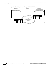
The Processor Switching Module
• line has the range 1–4 but depends on the number of lines on the back card.
For a feeder, you can activate only one line. For a stand-alone, you can activate more than one line if the
back card has multiple lines. One line must serve as the trunk to the ATM network. With an OC-3, T3,
or E3 card, remaining lines can serve as UNI ports to CPE.
Step 3 If necessary, modify the characteristics of a line by using cnfln.
Step 4 Configure logical ports for the physical line by executing addport. Execute addport once for each
logical port. Related commands are cnfport, dspports, and delport.
addport <port_num> <line_num> <pct_bw> <min_vpi> <max_vpi>
• port_num is the number for the logical port. The range is 1–32 for user-ports or 34 for inband ATM
PVCs that serve as management connections.
• line_num is the line number in the range 1–4 but depends on the type of uplink card.
• pct_bw is the percentage of bandwidth. The range is 0–100. This parameter applies to both ingress
and egress.
• min_vpi is the minimum VPI value. On a feeder, the range is 0–4095. On a stand-alone node, the
range is 0–255.
• max_vpi is the maximum VPI value. On a feeder, the range is 0–4095. On a stand-alone node, the
range is 0–255.
Using an example of 100% of the bandwidth on one logical port 1:
addport 1 1 100 1 200
where the first “1” is the logical port number; the second “1” is the line number on the PXM1 back card
to which you are assigning this logical port number; “100” is the percentage of bandwidth this port has
in both directions; and the VPI range is 1–200.
Step 5 If necessary, use cnfportrscprtn to modify port-level resources for a controller:
cnfportrscprtn <port_no> <controller> <ingress_%BW> <egress_%BW>
• <min_VPI> <max_VPI> <min_VCI> <max_VCI> <max_GLCNs>
• port_no is the logical port number in the range 1–32 for user-connections or 34 for inband ATM
PVCs for network management.
• controller is a string identifying the network controller—“PAR,” “PNNI,” or “TAG.”
• ingress_%BW is the percentage of ingress bandwidth in the range 0–100.
• egress_%BW is the percentage of egress bandwidth in the range 0–100.
• min_vpi is the minimum VPI in the range 0–4095.
• max_vpi is the maximum VPI in the range 0–4095.
• min_vci is the minimum VCI in the range 0–65535.
• max_vci is the maximum VCI in the range 0–65535.
• max_chans is the maximum GLCNS in the range 0–32767.
Step 6 On a stand-alone node, specify the cell header type as needed by executing cnfatmln.
cnfatmln <line_num> <type>
• line_num is the line number in the range 1–4.
• type is either 2 for UNI or 3 for NNI (the default).