


B-7
Cisco MGX 8230 Edge Concentrator Installation and Configuration
Release 1.1.31, Part Number 78-11215-03 Rev. B0, May 2001
AppendixB Cable Specifications
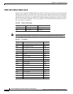
AC Power Cabling
AC Power Cabling
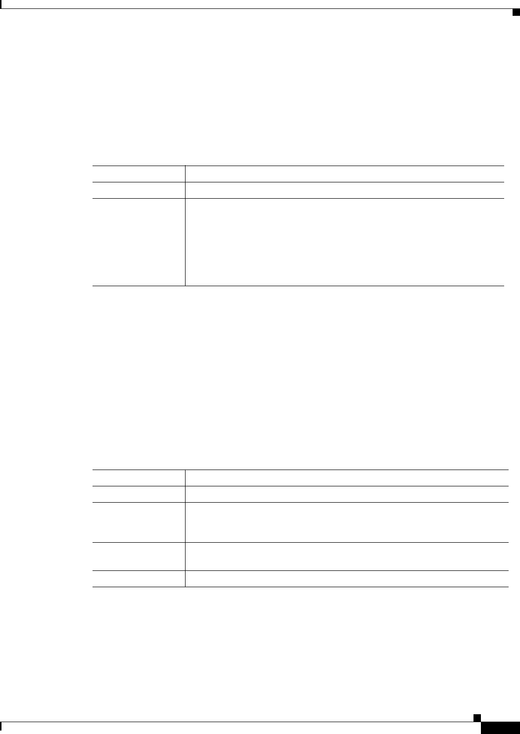
Either Cisco Systems or the customer can provide the AC power cord. See Table B-12 for the power
cords that Cisco can supply. In addition, you can special-order AC cables with other plugs or different
lengths. If you want to construct the power cord, it must mate with an IEC320 (C-14) 10/15A male
receptacle on the back of the AC power module.
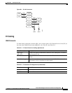
Control and Clock Cabling
This section describes the cables that can connect to the PXM-UI card.
Maintenance and Control Ports
The Maintenance (or Modem) port and the Control (or Console) port connect an MGX 8230 to an ASCII
terminal, workstation, or modem for remote alarm reporting or system monitoring. Refer to Table B-13
for a description of the cabling and Table B-14 for the pinout of the associated RJ45 connector.
Table B-12 AC Power Cables
Cable Parameter Description
Cable Provided with 8 feet (2.3 m) of 3-conductor wire with plug.
Plug (customer end) 20 A NEMA L620, 3-prong plug (domestic U.S.)
Need 15A NEMA 5-15 for US and Canada.
13 A 250 Vac BS1363, 3-prong fused plug (UK, Ireland)
CEE 7/7 (Continental Europe)
AS3112 (Australia/New Zealand)
CEI23-16/VII (Italy)
125V/15A North America
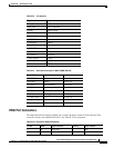
Table B-13 Maintenance and Control Port Cabling
Cable Parameter Description
Interface EIA/TIA-232—both are DTE ports.
Suggested Cable 24 AWG, 8-wire. A straight-through EIA/TIA-232 cable provides a terminal
or printer connection. For an interface with modems on either port, a null
modem cable may be necessary.
Cable Connector RJ45, subminiature, male. Table B-14 contains a list of the port pin
assignments.
Max. Cable Length 50 feet (15 m)