


1-10
Cisco MGX 8230 Edge Concentrator Installation and Configuration
Release 1.1.31, Part Number 78-11215-03 Rev. B0, May 2001
Chapter 1 Introducing the MGX 8230
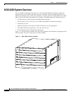
MGX 8230 System Overview
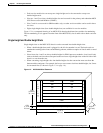
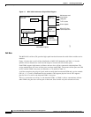
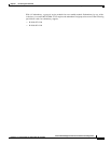
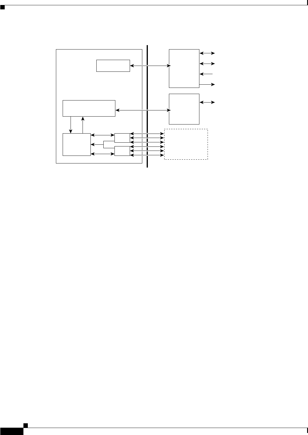
Figure 1-7 MGX 8230 Architecture Simple Block Diagram
Cell Bus
The MGX 8230 cell bus (CB) provides high-speed interface between the switch fabric and the service
modules.
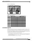
Figure 1-8 shows the overall cell bus distribution of MGX 8230 backplane and Table 1-1 lists the
specific cell bus allocation to each slot with respect to master and slave cell bus ports.
Each PXM1 supports eight master cell buses and one slave cell bus connected to the backplane. The
service modules have two slave cell bus ports, one from each PXM1. The master cell bus ports are CB0
to CB7 and the PXM1 slave ports are referred to as 7S and 8S in Table 1-1.
A cell bus comprises the group of signals used to transfer data between the PXM and a service module.
CB 0, 6, 1, 2, 4, and 3 are dedicated service modules, CB5 supports physical slot 6. CB7 supports
physical slot 13 as well as the alternate PXM1’s slave port.
There is a connection on cell bus 7 to the alternate PXM1. A PXM1 is able to communicate with the
other PXM1 using the slave cell bus port on that card. Slots 8 and 9 only refer to back card slots.
MGX 8230-PXM
front card
Processor
MGX 8230 midplane
PXM-UI
back card
Maintenance and
control ports
OC-3, OC-12,or
T3/E3 daughter card
Shared
memory
switch
CBC
CBC
OC-3, OC-12,or
T3/E3 feeder link
LAN ports
T1/E1 clocks
Alarm outputs
PXM
uplink
back card
Cell buses
to and from
service modules
38377