


A-10
Cisco MGX 8230 Edge Concentrator Installation and Configuration
Release 1.1.31, Part Number 78-11215-03 Rev. B0, May 2001
Appendix A Technical Specifications
FRSM-2T3E3 Specifications
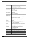
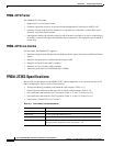
FRSM-2CT3 Framer
The FRSM-2CT3 line framer:
• Supports M13 or C-bit parity format.
• Performs required inversion of second and fourth multiplexed DS1 streams per ANSI T1.107.
• Generates loop-up code to the far-end device to loop back any of the DS1s or entire DS3 signal
stream by way of the FEAC channel.
• Automatically detects the incoming loop-up codes from the far-end device as well as loop back any
of the DS1s or entire DS3 signal stream back to the far-end device. The loopback occurs at the M13
framer chip.
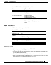
FRSM-2CT3 Line Alarms
For line alarms, the FRSM-2CT3 supports:
• Detection and generation of Remote Alarm Indicator (RAI) signal (also known as FERF and Yellow
signal)
• Detection and generation of Alarm Indication Signal (AIS)
• Detection of Out of Frame (OOF) condition
• Detection of Loss of Frame (LOS) condition
• Automatic generation of Far End Block Error (FEBE)
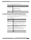
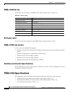
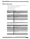
FRSM-2T3E3 Specifications
This section provides details for the FRSM-2T3E3. Where appropriate, it has separate sections for T3
and E3 technologies. Topics consist of the following:
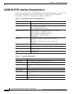
• Transport technology standards with which the card complies (Table A-11)
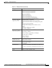
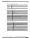
• General physical attributes of the card, such as LEDs on the faceplate (Table A-12)
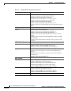
• Line and framer characteristics for T3 operation (Table A-13 and “T3 Framer Level”)
• Line and framer characteristics for E3 operation (Table A-14 and “E3 Framer Level”)
• Line alarms (“FRSM-2T3E3 Line Alarms”)
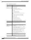
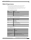
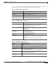
Table A-11 Frame Relay Interface Standards
Interface Standard
Frame Relay Interface ANSI T1.618, 2-octet header
ATM Layer CCITT I.361 and ATM UNI v3.1
AAL Layer AAL5 ITU-T I.363
FR-Cell Interworking Per ITU-T I.555 and I.36x.1, as summarized in ATM-to-Frame Relay
Interoperability Implementation Agreement v 1.0