


1-6
Cisco MGX 8230 Edge Concentrator Installation and Configuration
Release 1.1.31, Part Number 78-11215-03 Rev. B0, May 2001
Chapter 1 Introducing the MGX 8230
MGX 8230 System Overview
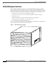
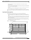
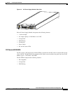
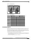
Figure 1-3 MGX 8230 Card Cage, Front View
Chapter 3, “Site Preparation” and Chapter 4, “Enclosure Installation” contain additional information on
installing racks and the MGX 8230 chassis.
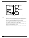
MGX 8230 Power System
The MGX 8230 power system is designed with distributed power architecture centered around a
-48 VDC bus on the system backplane. The -48 VDC bus accepts redundant DC power from either a -42
to -56 VDC source via optional DC power entry modules (PEMs) or from a 100 to 120 or a 200 to 240
VAC source via the optional AC Power Supply Tray. The MGX 8230 backplane distributes power via
connectors on the - 48 VDC bus to each hot-pluggable processor or service module. Each card
incorporates on-board DC-DC converters to convert the -48 VDC from the distribution bus voltage to
the voltages required on the card.
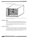
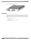
Optional AC Power Supply
For an AC-powered MGX 8230, an optional AC power supply tray is attached to the bottom of the MGX
8230 card cage at the factory. The AC power supply tray is one rack-unit high, and can hold up to two
AC Power Supply modules. Each AC Power Supply module can provide up to 1,200W at -48 VDC and
has its own AC power cord and power switch. Figure 1-4 shows the rear view of an optional AC Power
Supply module. The power supplies can be configured as 1+1 redundant. If no redundancy is desired, an
AC tray with one AC power supply and one AC power cord can also be ordered.
26268