


4-12
Cisco MGX 8230 Edge Concentrator Installation and Configuration
Release 1.1.31, Part Number 78-11215-03 Rev. B0, May 2001
Chapter4 Enclosure Installation
Rack Mounting an MGX 8230
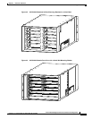
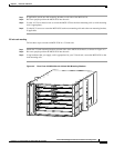
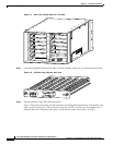
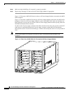
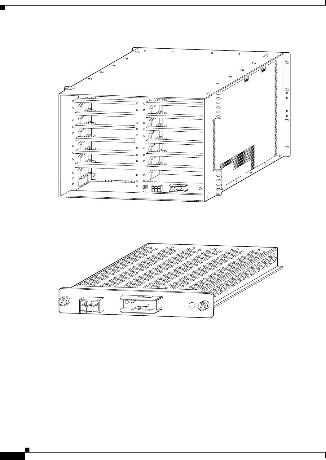
Figure 4-7 Rear View of MGX 8230 with 1 DC PEM
Step 2
Locate the pluggable terminal block (TB1) on the DC PEM to which you are connecting source power.
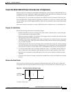
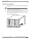
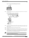
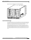
Figure 4-8 DC Power Entry Module, Rear View
Step 3
Note the polarities of the TB1 connection points.
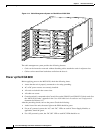
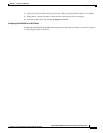
Figure 4-9 illustrates the polarity of each connection on the pluggable terminal block. The numbers start
with 1 on the left and go to 3. The connection at the left is for the –48 VDC wire. The middle wire is
Safety Ground. The connection at the right is for the positive return wire (for the –48 VDC).
23826
48 VDC
30A
TB1
1
2
3
OFF
48 VDC
30A
TB1
1
2
3
OFF
17275