


5-14
Cisco MGX 8230 Edge Concentrator Installation and Configuration
Release 1.1.31, Part Number 78-11215-03 Rev. B0, May 2001
Chapter 5 Configuring the MGX 8230 Shelf
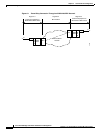
MGX 8230 MGX to BPX Feeder
Note If you configure MGX 8230 PXM features at the back card, select the Configure Card options by
clicking with the left mouse button on the MGX 8230 PXM back card but away from the connectors.
If you successfully select the card features, an outline of the entire back card lights up. To select the
Configure Line features, click on the back card near the connectors. If you select the line features,
an outline around the connectors lights up. Similarly, in the front view, select either a port LED for
line configuration or a nonspecific area of the MGX 8230 PXM front card for card configuration.
Specifying the Feeder Application
To specify that the MGX 8230 operate as a feeder to a BPX series switch:
Step 1 Click with the left mouse button on the MGX 8230 PXM so that the card outline lights up.
Step 2 Click on the Configure option at the top of the CiscoView - Main window; then click on the highlighted
“card” choice that appears under “Configure.” The Configure Card box appears. Next to the
“CATEGORY” label, the menu button shows “Card.”
Step 3 Click on Card to display the node configuration options.
Step 4 Select PAR Configuration. The Configure PAR window opens.
Step 5 Click on the menu button next to the CATEGORY field to display the PAR topics.
Step 6 Select PAR SW Configuration. The PAR Configuration box shows the defaults of “false” for VS/VD and
“routing” for Node Type. Change the selection to “feeder.”
Step 7 Select Modify at the bottom of the box.
Step 8 Select Cancel to exit the PAR Configuration box or select another PAR topic at the menu button next to
the CATEGORY field.
Activating a Physical Line for the Uplink
To activate a line for the uplink:
Step 1 Click on the LED that corresponds to the MGX 8230 PXM line you want to activate. For the feeder
application, only port 1 is selectable. If you correctly select the LED of an inactive line, an outline of
the LED lights up. If an outline of the card lights up, you have selected the card rather than the port.
Step 2 Click on the Configure option at the top the screen then the line option in the subsequent pull-down list.
The Configure Line window appears and shows the selected line with its current characteristics.
Step 3 Change appropriate line characteristics as needed, then select the LineEnable button and change the state
to “enable.”
Step 4 Click on the Modify button to transmit any configuration changes and enable the line.