


B-6
Cisco MGX 8230 Edge Concentrator Installation and Configuration
Release 1.1.31, Part Number 78-11215-03 Rev. B0, May 2001
AppendixB Cable Specifications
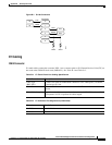
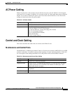
DC Power Cabling
DC Power Cabling
DC Power connections are made to the DC Power Entry Modules at the rear of the MGX 8230. See Table
B-11 and Table B-12 for acceptable cable and wire types. Cisco normally does not provide wiring for
DC-powered systems. See Table B-11 for details on DC wiring.
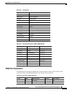
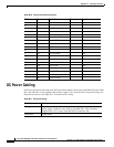
4 RD Receive Data + DCE
29 -
6 ST Send Timing +
31 -
2 RT Receive Timing +
27 _
6 TT Terminal Timing + DCE
13 -
3CADCE Available+DCE
28 -
8TADTE Available+DTE
33 -
10 LA Loop Ckt A + DTE
35 -
12 LB Loop Ckt B + DTE
37 -
5 LC Loop Ckt C + DCE
30 -
SG Signal Ground
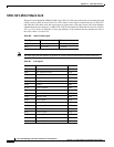
Table B-10 Pinouts for SCSI-II Connector
Pin No. Name Signal Function Polarity Signal Source
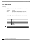
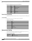
Table B-11 DC Power Wiring
Cable Parameter Description
Wiring Three conductor, 10 AWG recommended wire gauge, min. 60°C insulation
rating, copper conductors only. Solid or stranded wires. Wire insulation
stripped back 0.25” (6 mm) at the MGX 8230 connector end.
Connection EURO Block.