


2-46
Cisco MGX 8230 Edge Concentrator Installation and Configuration
Release 1.1.31, Part Number 78-11215-03 Rev. B0, May 2001
Chapter2 Module and Service Descriptions
Frame Relay Service Modules
• A single T1/E1 CESM card can provide standby redundancy for all active CESM cards of the same
type in the shelf (1:N redundancy), with SRM.
• CESM cards are supported by standards-based management tools, including Simple Network
Management Protocol (SNMP), Trivial File Transfer Protocol (TFTP) for configuration and
statistics collection, and a command-line interface. Cisco WAN Manager also provides full
graphical user interface (GUI) support for connection and equipment management.
1:N Redundancy for the CESM T1/E1
Redundancy for the AX-CESM-8T1 and AX-CESM-8E1 is available through the MGX-SRM-3T3/C.
• 1:N redundancy requires that the group contain one redundancy back card.
• The redundancy back card must be the special R-RJ45 version (AX-R-RJ48-8T1-LM or
AX-R-SMB-8E1-LM).
For information on installation requirements, refer to the Service Resource Module, page 2-12. For
configuration requirements, see the “Service Resource Module” section on page 6-49.
For instructions on how to use the CiscoView application to configure redundancy, refer to the
CiscoView user-documentation.
Card Combinations
A card set has an AX-CESM-8T1 or AX-CESM-8E1 front card and one of the following back cards:
• AX-RJ48-8T1-LM
• AX-R-RJ48-8T1-LM (for redundancy support)
• AX-RJ48-8E1-LM
• AX-SMB-8E1-LM
• AX-R-SMB-8E1-LM (for redundancy support)
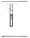
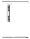
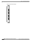
CESM T1/E1 Illustrations
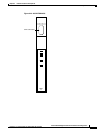
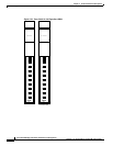
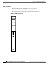
• Figure 2-24 on page 2-48 shows the Front Cards for the Eight-Port CESM (T1 and E1).
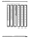
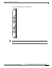
• Figure 2-25 on page 2-49 shows the RJ-48 and SMB Back Cards for the MGX-CESM-8T1E1.
LED Indicators for the Eight-Port CESM
The description of the LEDs on the eight-port CESM correspond to the illustration in Figure 2-24 on
page 2-48.
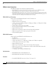
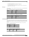
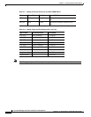
Table 2-13 LED Indicators for Eight-Port CESM
Type of LED Color Meaning
PORT LEDs Green Green indicates the port is active.
Red Red indicates a local alarm on the port. Off indicates
the port has not been activated (upped).
Yellow Yellow indicates a remote alarm on the port. Off
indicates the port has not been activated (upped).
ACT LED (Active) Green On indicates the card set is in active mode.