


3–36 Creating Storagesets
3. Show the devices that are assigned to the controller. Use the following syntax:
SHOW DEVICES
4. Locate each device assigned to the controller and record its location on your copy
of the cabinet template. Use the following syntax:
LOCATE device_name
The LOCATE command causes the device’s LED to flash continuously.
5. Turn off the LED using the following syntax:
LOCATE CANCEL
The controller names each device based on its PTL location. See the next section for
details about the controller’s PTL addressing convention. Repeat step 2 through step 4
for each controller or dual-redundant pair of controllers.
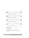
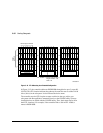
6. After you have mapped the devices to your cabinet template, create the storageset
map by circling each group of disk drives that you want to combine into a
storageset or put into the spareset. Label each group with a storageset name, for
example: RAID1 for a RAIDset; Mirr1 for a mirrorset; and Stripe1 for a stripeset.
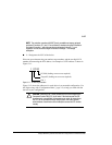
Device PTL Addressing Convention within the
Controller
Your controller has six SCSI–2 device ports. Each device port supports one to four
devices or “targets” per port. Every device uses LUN 0, except remote devices in a
DT configuration, which can use nonzero LUN values.
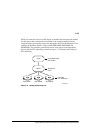
The controller identifies the location of devices based on a PTL numbering scheme.
The controller uses the PTL address to locate devices.
■ P—Designates the controller’s SCSI device port number (1 through 6).
■ T—Designates the target ID number of the device. Valid target ID numbers for a
single-controller configuration and dual-redundant controller configuration are 0
through 15, excluding ID numbers 4 through 7. ID numbers 6 and 7 are used for
the controllers; ID numbers 4 and 5 are never used.