


148 Installing System Components
3
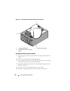
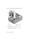
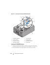
Slide the power supply distribution board to the right until the blue release
pin locks into place, securing the board.
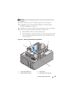
4
Connect the four power cables from the system board to the connectors on
the power supply distribution board. See Figure 3-39.
5
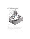
Install the power supply distribution board shroud.
Slide the edges of the shroud under the shroud alignment guides until the
release latch locks into place. See Figure 3-38.
6
Install the processor shroud. See "Installing the Processor Shroud" on
page 74.
7
Install the expansion card shroud. See "Installing the Expansion Card
Shroud" on page 75.
8
Close the system. See "Closing the System" on page 70.
9
Place the system upright and on its feet on a flat, stable surface.
10
Install the redundant power supplies. See "Installing a Redundant Power
Supply" on page 77.
11
Reattach any peripherals, then connect the system to the electrical outlet.
12
Turn on the system and attached peripherals.
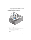
SAS/SATA Backplane
If your system has front-loading hot-plug hard drives (when available), the
system contains a SAS/SATA backplane board to which the hard drives
connect.
Removing the SAS/SATA Backplane
CAUTION: Only trained service technicians are authorized to remove the system
cover and access any of the components inside the system. See your Product
Information Guide for complete information about safety precautions, working
inside the system, and protecting against electrostatic discharge.
1
Turn off the system and attached peripherals, and disconnect the system
from the electrical outlet and peripherals.
2
Remove the front-drive bezel. See "Removing the Front Drive Bezel" on
page 66.
3
Open the system. See "Opening the System" on page 68.