


74 Installing System Components
5
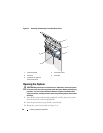
Disconnect the SATA cable(s) from the system board and remove the
cable(s) from the cable guides. Lay the SATA cables away from the
processor shroud.
6
If present, disconnect any SAS cables from the SAS card to the hard drives
and remove the cables from the cable guides. Lay the SAS cables away
from the processor shroud.
7
Disconnect all power cables to any drives in the system.
8
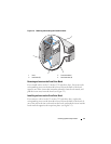
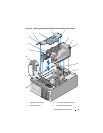
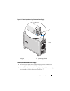
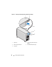
Pull the release latch in the direction of the arrow. Holding the latch and
the shroud touch point, lift the shroud up and out of the chassis. See
Figure 3-6.
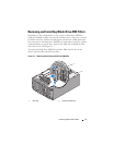
Installing the Processor Shroud
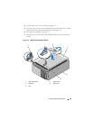
1
Carefully lower the shroud into the chassis, inserting the front shroud lip
under the shroud alignment guide, and inserting the shroud alignment
tabs into the tab slots in the chassis. Make sure that no cables are pinned
under the bottom edges of the shroud, and press down on the shroud until
the shroud latch locks into place. See Figure 3-6.
2
Route the SATA cable(s) under the cable guides, and connect the SATA
cables to the SATA connectors on the system board. See Figure 3-11 for
SATA hard drive cable-routing guidelines and Figure 3-22 for SATA optical
drive cable-routing guidelines.
3
Route the ribbon cables under the ribbon cable slot, and connect the
cables to the connectors on the system board. See Figure 3-17 for ribbon
cable routing guidelines.
4
If applicable, route the SAS-card cables through the shroud cable guides,
and connect the cables to the hard drives. See Figure 3-12 for cable routing
guidelines.
5 shroud touch point 6 rear shroud tab slots (2)
7 tab slots (2) 8 front shroud tab slot
9 shroud alignment guide 10 front shroud lip
11 release latch 12 cable guides (4)
13 shroud latch 14 front shroud alignment tab
15 gripping points