


154 Installing System Components
4
Remove the processor shroud. See "Removing the Processor Shroud" on
page 72.
5
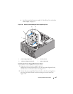
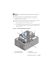
Depending on your configuration, disconnect the following cables from
the system board. See
Figure 6-1
for connector locations.
• Three power-supply cables from the PWR1, PWR2, and PWR3
connectors
• I/O panel cable from the
CTRL_PNL
connector
• SATA cable(s) from the SATA connector(s)
• Diskette data cable from the FLOPPY connector
• PATA data cable from IDE connector
• Expansion card fan cable from the FAN1 connector
• System fan cable from the FAN2 connector
• SAS LED cable from the PERC_LED connector
• SAS/SATA backplane cable from BP_12C connector
• Intrusion switch cable from the INTRUSION connector
6
If applicable, remove all expansion cards and any attached cables. See
"Removing an Expansion Card" on page 107.
7
If applicable, remove the RAC card. See "Removing the RAC Card" on
page 117.
8
If applicable, remove the SAS controller card. See "Removing a SAS
Controller Card" on page 114.
9
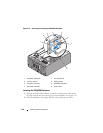
Remove the internal USB memory key, if present. See Figure 6-1 for the
USB socket location.
10
Remove the TOE hardware key, if present. See Figure 6-1 for the
TOE_KEY socket location.
11
Remove all memory modules. See "Removing Memory Modules" on
page 132.
NOTE: Record the memory-module socket locations to ensure proper
reinstallation of the memory modules.
CAUTION: The processor and heat sink can become extremely hot. Allow
sufficient time for the processor and heat sink to cool before handling.