


DISASSEMBLY AND ASSEMBLY
Rev. B
3-11
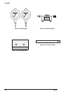
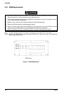
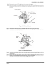
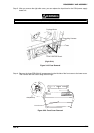
Step 5: Disconnect the narrow FPC cable from white connector (lock-type).
Step 6: Move the carriage to around 90
th
column, remove the two CP(S-P1)(M4X7) screws securing the
printhead and remove the CP(S-P1)(M3X6) screw securing the ground FPC, then remove the
printhead.
Narrow FPC Cable
C P (S -P 1 )(M 3 X 6 )
C a rri a g e
C P (S -P 1 )(M 4 X 7 )
P rinthead
Figure 3-12. Printhead Removal
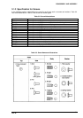
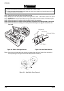
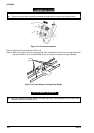
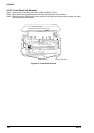
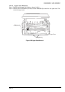
Step 7: Disconnect the white connector for the paper width (PW) sensor on the ribbon mask.
Step 8: Remove the two shafts securing the ribbon mask to the carriage using a hexagon head screw
wrench, then remove the ribbon mask.
PW Sensor
C onnector
R ibbon
Mask
S h a fts
Figure 3-13. Ribbon Mask Removal
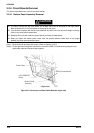
Step 9: Install the new printhead, ribbon mask, and cable protection sheet by following Steps1 to 9 in the
reverse order.
Step 10: Replace the ribbon mask with a new one. Set the cable of the paper width sensor as shown in
Figure 3-13. After installation, check that the ribbon mask is a little loose.
Step 11: Install the new printhead (torque the screws to 12 + 1 kg cm). Replace the head cable protection
sheet with a new one, then connect the head cables to the connector.