


DFX-8500
Rev. B
3-2
8
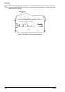
3.2.5 Interlock Switch and Cover Open Sensor Assembly Removal
Step 1: Remove the upper case. (Refer to Section 3.2.3.4)
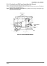
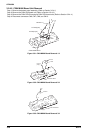
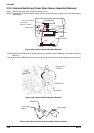
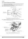
Step 2: Disconnect the interlock switch cable and the cover open sensor cable from the junction board
respectively.
C over O pen Sensor
In te rlo c k S W .
CN3
C onnector
Junction Board
C 204 M AIN Board
W hite: 2-pin
R ed: 3-pin
C over O pen
Sensor C onnector
Figure 3-38. Interlock Switch Assembly Removal
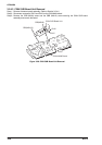
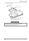
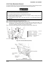
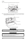
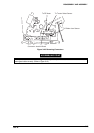
Step 3: Remove the CBB (M4x10) screw securing the interlock switch assembly to the lower case. and
remove it.
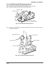
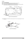
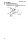
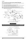
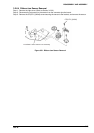
Step 4: Remove the CBB (M3x10) screw securing the cover open sensor to the upper case. and remove
it.
In te rlo c k S W
Assem bly
CBB(M 4X10)
Low er C ase
Figure 3-39. Interlock Switch Assembly Removal
Upper Case
CBB(M 3X10)
C over O pen
Sensor
Figure 3-40. Interlock Switch and Cover Open Sensor Removal