


ADJUSTMENT
Rev. B
4-
9
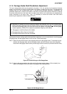
4.1.6 Platen Angle Adjustment
This section describes the platen angle adjustment. The platen must be at a right angle to the carriage
assembly. This adjustment is required when the platen is removed or replaced or when the two hexagonal
screws securing the platen to both side frames are loosened. Do not remove the printer mechanism from the
lower case. (If remove the printer mechanism from the lower case, the adjust value will be out of order when
you reassemble the printer mechanism to the lower case.) Also, it is necessary to remove the tension roller
shaft be fore performing this adjustment. (Refer to Section 3.2.6.7)
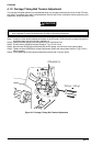
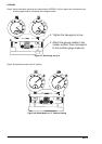
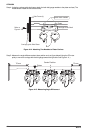
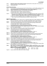
The parallelism is adjusted so that the difference between the distances (from the rear carriage guide
shaft to the platen measured at the two positions shown in Figure 4-7) is less than + 0.015 mm. Since
this value is extremely small, you must use the two dial gauges, dial gauge base, and dial gauge
master supplied by EPSON. Do not adjust the parallelism using any other method.
;
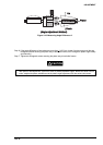
Dial gauge #F610 (Part No. B1019466)
;
Dial gauge base #F611 (Part No. B1019467)
;
Dial gauge master #F612 (Part No. B1019468).
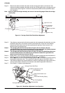
Step 1: Perform the carriage guide shaft parallelism adjustment. (Refer to section 4.1.5) After the adjustment
is finished, leave the dial gage unit on the carriage.
Step 2: Remove the pull tractor sensor.(Refer to Section 3.2.6.10.)
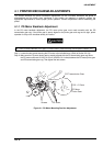
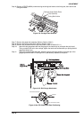
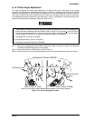
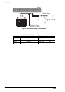
Step 3: Loosen (but do not remove) the two hexagonal screws securing the platen stay to both side frames.
CAUTION
H exagonal Screw s (M 4X8)
Platen Stay (R)
Platen Stay (L)
Positioning Tab
Positioning Tab
Side Fram e R SideSide Fram e L Side
Figure 4-13. Loosing Hexagonal Screws