


OPERATING PRINCIPLES
Rev. B
2-2
5
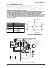
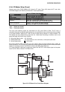
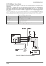
2.3.4 CR Motor Drive Circuit
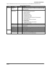
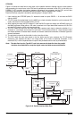
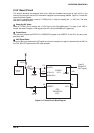
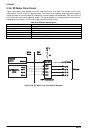
Figure 2-19 shows the internal circuit for the CR motor,Table 2-6 provides the CR motor specification, and
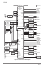
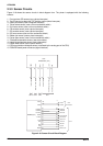
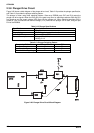
Figure 2-20 shows a block diagram for the CR motor drive circuit.
An STK681-050 (IC1) bipolar driver IC drives the CR motor. It has built-in bipolar switching transistors and a
current limiter. A comparator IC uPC393C (IC3) monitors the current in the CR motor driver IC (IC1). If the
current exceeds the set value, it is fed back to the gate array (E05B36), and then the gate array outputs the
signal for the current setting transistors (Q5, Q6, and Q7).
When the printer is turned on, CPU analog port AN2 measures the isolation resistance in the CR motor. If the
isolation resistance is equal or less than 2.2 K ohms, the printer change the status to the carriage error.
If the printer cover is open during power on, the CR motor driver power is cut by the interlock switch.
The ENCA pulse that the carriage encoder outputs is input to general purpose port CRENCA of the gate
array, and the ENCB pulse that the carriage encoder outputs is input to general purpose port CRENCB of the
gate array. The gate array counts these pulses using the internal counter and determines the amount and
direction of motor rotation.
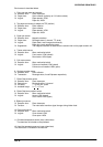
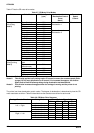
Table 2-6. CR Motor Specifications
Specification Description
Form DC servo motor
Supply Voltage 37 VDC
Internal Coil
Resistance
1.66 ohms (+ 10 %)
Current
Consumption*1)
Accerelation / Deceraration:
4.6 A (AV.)
Constant Speed:
2.5 A (AV.)
*1): at Super draft printing, + 10 %
Motor
Q2
Q3Q1
Q4
VP3 (+37 VDC)
GP3 (GND)
R1
Figure 2-19. CR Motor Internal Circuit
E05B36 (IC1)
CRAX
STK681-050(IC1)
IN_A
VP3
VCC1
OUT1
CR B
Vref
ZD1
4.3 V
A OUT
AIN+
AIN-
CRI0
CRI1
CRI2
CRENCB
CRENCA
VCC1
OUT2
CR A
IN_B
IN_C
IN_D
DRV
Board
MAIN
Board
CRCLK
Q16,
Q17,
Q18,
Q19
VX
CRBX
CRCX
CRDX
CLK
Q34,
Q35,
ZD2
VX
CRCLM
Q5,
Q6,
Q7
GPGP
Vref
+5V
GP3
GP3
Vx
CPU
TMP85C061
(IC2)
AN2
CRINS
CRCLM
D3
uPC393C(IC3)
Partical Pressure
Circuit
Interlock SW
Carriage
Motor
Carriage Encoder Sensor
ENCA
ENCB
Figure 2-20. CR Motor Drive Circuit Block Diagram