


APPENDIX
Rev. B
A-1
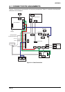
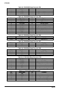
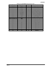
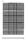
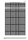
A.1 CONNECTOR PIN ASSIGNMENTS
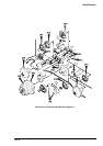
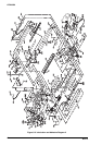
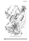
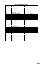
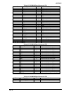
Figure A-1 illustrates the interconnection of the primary components. Table A-1 summarize the description
and sizes of the connectors.
CN1(3)
CN5(2)
CN3(12)
CN2(6)CN4(8)
Fan
C204 PSB/PSE
CN3(2)CN4(4)CN5(14)CN9(7)
CN1(30)
CN2(20)
C204 DRV-B
CN1(30)
CN3(20)
CN2(8)
CN8(8)
CN6(6)
CN12(36)
CN13(7)
IEEE1284
EIA-232D
CN11(36)
TYPE-B
CN10(8)
CN7(12) CN14(50x2) CN16(7)
CN15(6)
CN2(7)
CN1(6)
C204 SUB
C204 MAIN
C204 DRV
CN2(50)
CN3(6)
CN1(50x2)
Printer Mechanism
C204 PNL
CN1(7)
CN2(7)
Cover Open Sensor
CR Encoder
Junction Board
Printhead
Paper Cutter
Unit
AC Input
Figure A-1. Cable Connection