


TROUBLESHOOTING
Rev. B
5-21
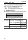
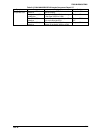
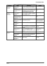
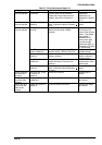
Table 5-6. C204 MAIN/DRV/DRV-B boards Component Repair 6/7
Symptom Cause Checkpoint Solution
The head fan
operation is
abnormal.
IC1 on the C204
MAIN board is
defective.
Observe the PG motor phase signal at
pins 163 (FANA) and 164 (FANAX) of
IC1.
Replace IC1.
Q10 or Q11 on the
C204 MAIN board is
defective.
Observe the head fan phase drive
voltage level for pins 25 (HFANA) and
17 (HFANB) of CN1. (The normal
voltage is approximately 37 VDC.)
Replace Q10 or
Q11.
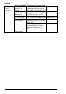
The PG motor
operates
abnormally.
IC1 on the C204
MAIN board is
defective.
Observe the PG motor phase signal at
pins 10 (PGA), 12 (PGB), 14 (PGAX),
and 13 (PGBX) of IC1.
Replace IC1.
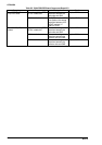
The common
switching transistor on
the C204 DRV board
is defective.
Check the collector voltage of Q11. Replace Q10 or
Q11.
The phase switching
transistor on the C204
DRV board is
defective.
For transistors Q12 - Q15, observe the
output signal (collector).
if there is no output
signal, replace the
abnormal transistor.
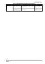
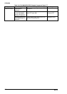
Fuse F2 on the C204
DRV board is
defective.
Check if fuse F2 is defective. Replace F2.
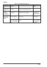
The PG sensor is
defective.
Observe the PG sensor output signal at
pins 35 (PGENCA) and 34 (PGENCB)
of CN14.
Replace the PG
sensor.
The PG home
position sensor is
defective.
Observe the PG HP sensor signal level
for pin 36 (PGHOME) of CN14.
(PG home = LOW level; other = HIGH
level.)
Replace the PG
home position
sensor.
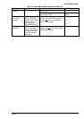
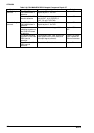
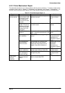
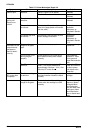
The plunger is
defective.
Fuse F3 is defective Check if fuse F3 is defective. Replace F3.
IC1 on the C204
MAIN board is
defective.
When paper is loaded into the printer,
look at the switching signal at pins 16
(PLP) and 17 (PLN)of IC1.
Replace IC1.
Plunger drive
transistor on the C204
DRV board is
defective.
Observe the Q31 collector voltage at
paper loading.
Replace Q31, Q30,
or Q32.