


DFX-8500
Rev. B
3-3
6
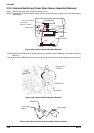
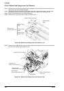
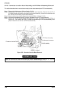
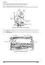
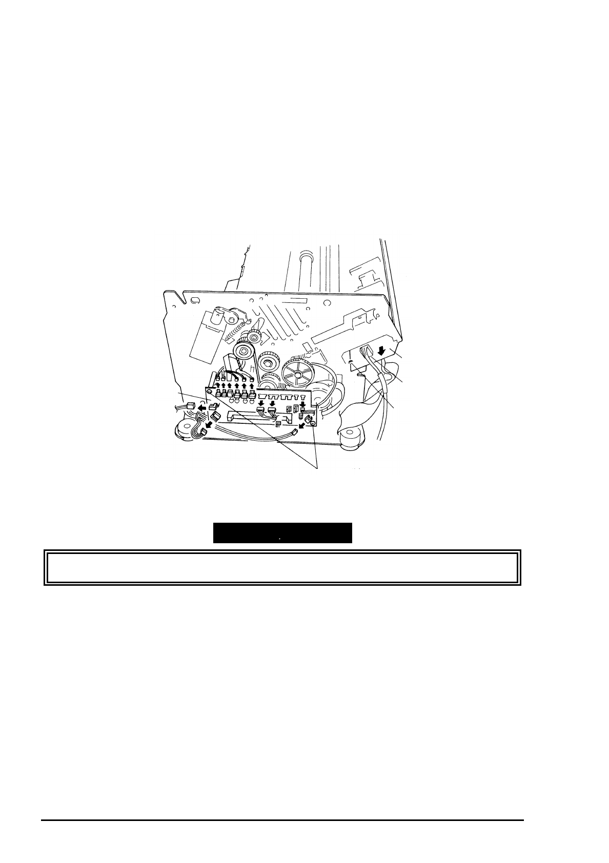
3.2.6.5 Connector Junction Board Assembly and FPC Board Assembly Removal
This section describes how to remove the connector junction board assembly and FPC board assembly.
Step 1: Remove the left side cover. (Refer to Section 3.2.3.2)
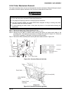
Step 2: Disconnect all the cables from the connector junction board assembly. Remove the two CP (S-
P1) (M3x6) screws securing the connector junction board assembly to the printer mechanism and
then remove the connector junction board assembly.
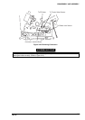
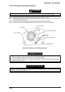
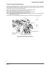
Step 3: Remove the front/rear tractor select lever assembly. (Refer to Section 3.2.6.2)
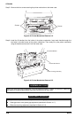
Step 4: Disconnect the connector for the CR sensor (encoder) from the FPC board assembly.
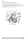
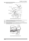
Step 5: Remove the 2 CBS (M3x8) screws securing the FPC cover and remove the cover (Refer to
Figure 3-10). Then remove the CPS(P-1) (M3x6) screw securing the FPC board assembly to the
printer mechanism and remove the FPC board assembly.
C onnector Junction Board
FPC Board Assem bly
C R Encoder Connector
CPS(SP-1) (M 3x6)
CPS(P1)(M 3x6)
Figure 3-52. Connector Junction Board Removal
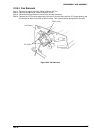
ASSEMBLING POINT
When you connect the cables to the connector junction board assembly, note that the matching
connectors have the same color and number of pins (Refer to APPENDIX Figure A-15.).