


DFX-8500
Rev. B
2-2
2
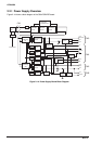
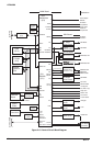
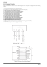
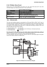
2.3.3 Sensor Circuits
Figure 2-18 shows the sensor circuits in block diagram form. The printer is equipped with the following
sensors:
1. Front and rear PE sensors (use a photo interrupter)
2. Top PE sensor (to detect the TOF position, uses a photo interrupter)
3. Paper jam sensor (uses a magnetic transistor)
4. Tractor select sensor (uses a micro mechanical switch)
5. Pull tractor sensor (uses a micro mechanical switch)
6. CR encoder sensor (uses a photo interrupter)
7. PG encoder sensor (uses a photo interrupter)
8. PG home sensor (uses a micro mechanical switch)
9. Ribbon jam sensor (uses a photo interrupter)
10. Cover open sensor (uses a micro mechanical switch)
11. Printhead temperature sensor (uses a thermistor)
12. Head fan temperature sensor (uses a thermistor)
13. Paper width sensor (uses a photo reflector)
14. CR motor isolation resistance sensor (monitored by the analog port of the CPU)
15. PSB/PSE board power off sensor (signal interface)
E05B36 (IC1)
CN4
ENCA
ENCB
CR Encoder
3
4
CN14
PGENCA
PGENCB
35
34
148
149
ENCA
ENCB
PGENCA
PGENCB
28
25
CN14
CPU
TMP95C061 (IC2)
AN0
AN1
AN2
AN3
202122 23
Printhead Temperature
Head Fan Temperature
CR Motor Insulation
Paper Width
INT5
35
Cover Open
CN3
1
CN1
221929
Tractor Select
Pull Tractor
28
29
TRSEL
PTRCT
19
20
Paper Jam
Front PE
30
31
PJAM
FPE
21
22
Rear PE
Top PE
32
33
RPE
TPE
23
24
PG Home
Ribbon Jam
37
RBJAM
29
3618
PG Home
18
CN10
XNMI
10
POFF (SD)
8
Figure 2-18. Sensor Circuit Block Diagram