


DISASSEMBLY AND ASSEMBLY
Rev. B
3-41
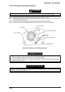
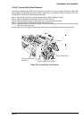
3.2.6.9 Tension Roller Shaft Removal
This section describes how to remove the tension roller shaft. It is better to remove the tension roller shaft
with the paper bail assembly removed; however, removing it is not required. (Refer to Section 3.2.6.7.) for
instructions on how to remove the paper bail assembly.)
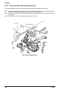
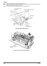
Step 1: Remove the connector junction board assembly. (Refer to Section 3.2.6.5.)
Step 2: Remove the paper bail assembly. (Refer to Section 3.2.6.7.)
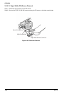
Step 3: While pushing the tension pulley to the front, remove the CR timing belt.
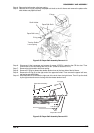
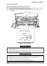
Step 4: Remove the upper paper guide. (Refer to Section 3.2.6.8.)
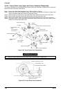
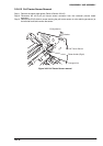
Step 5: Using tweezers, unlock the locking tab of the tension roller gear at the left end of the tension roller
shaft, and remove the gear.
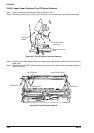
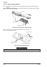
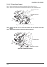
Step 6: Remove the E-ring (6) on the left end of the tension roller shaft and remove the shaft holder.
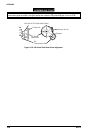
E-ring(6)
Tension R oller G ear
Tension R oller Shaft H older
Tension R oller Shaft
Assem bly
Left
R ight
Figure 3-59. Tension Roller Gear Removal