


DFX-8500
Rev. B
2-3
0
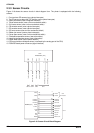
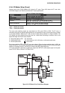
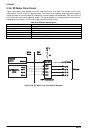
2.3.6 RF Motor Drive Circuit
Figure 2-24 shows a block diagram of the RF motor drive circuit, and Table 2-10 provides the RF motor
specifications. The RF motor is a stepping motor. The control circuit performs open-loop phase switching
control according to the timing data for acceleration, constant speed, and deceleration. CPU ports PG10 to
PG13 output the motor phase switching signals. The control method is not equipped with a hold circuit for
changing the motor phase. The RF motor rotates when the carriage moves.
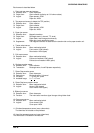
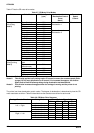
Table 2-10. RF Motor Specifications
Specification Description
Form 4-phase, 48-pole, PM pulse motor
Supply Voltage 37 VDC (applied to the drive circuit)
Internal Coil Resistance 150 ohms + 10 % per phase at 25
o
C
Frequency 720 pps
Current Consumption Driving: 0.10 A (average)
Driving Method Constant voltage driving, 2-2 phase drive
TMP95C061A
(IC2)
PG10
PG11
PG12
PG13
Q22
Q23
Q24
Q25
PNP Transistor x4
RF A
RF B
RF C
RF D
MAIN
Board
DRV
Board
E05B36
(IC1)
RFCOM
Q20,Q21
VP 3
F1
RF COM
RF Motor
Figure 2-24. RF Motor Drive Circuit Block Diagram