


DFX-8500
Rev. B
1-22
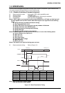
1.3.3 Serial Interface
Synchronization : Asynchronous
Signal level (ELA-232D) :
MARK (logical 1) : -3Vto-25V
SPACE (logical 0) : +3Vto+25V
Word length :
Start bit : 1 bit
Data bit : 8 bit
Parity bit : Odd, Even, Non, of Ignore
Stop bit : 1 bit or more
Baud rate : 2400, 4800, 9600 or 19200 bps
Handshaking : DTR signal or X-ON / X-OFF
DTR=MARK, X-OFF : Indicates that the printer cannot receive data.
DTR=SPACE, X-ON : Indicates that the printer is ready to receive data.
Note: The DTR signal is MARK and X-OFF code (DC3, 13h) is transmitted when the rest of the
input buffer becomes 256-byte. The DTR signal is SPACE and X-ON code (DC1, 11h) is
transmitted when the rest of the input buffer is regained 256-byte.
Error handling : When parity error is detected, the received byte is changed to the
"*" character code. Overrun error and framing error are ignored.
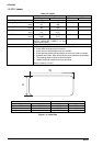
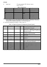
Connector : 25 pin sub-miniature D-shell connector (female)
Connector pin assignment and signals : Refer to Table 1-12.
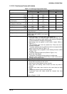
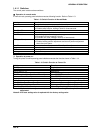
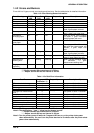
Table 1-12. Signal and Connector Pin Assignment (EIA-232D)
Pin No. Signal Name In / Out* Functional Description
2 TXD Out Transmit data.
20 DTR Out Indicates that the printer is ready to receive data or not.
11 REV Out Connected directly to the DTR signal.
4 RTS Out Request to send. always SPACE level when the printer is
powered on. Pulled up to +12 V via 4.7K-ohm resistor.
3 RXD In Receive data
7 Signal GND - Signal GND
1 Chassis
GND
- Chassis GND
Other NC - Not used. Not connected.
Note: * In/Out refers to the direction of signal flow from the printer’s point of view.
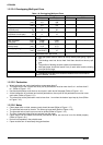
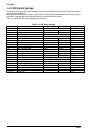
1.3.4 Optional Interface
Type-B and Type-B level 2 optional interfaces are available (Refer to Table 1-1.).