


DISASSEMBLY AND ASSEMBLY
Rev. B
3-1
9
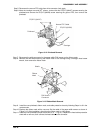
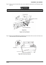
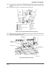
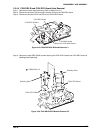
Step 3: From the left side, remove the two CPB(O)(M4X8) screws securing the green and yellow earth
cables between the bottom plate of the printer mechanism and the earth on the bottom panel
assembly.
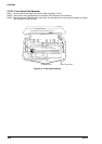
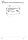
Step 4: Disconnect the 6 connectors, (1) through (6) as shown in Figure 3-24.
Earth C able
Earth C able
3
2
6
1
5
4
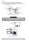
Flat C able Connector (50-pin): M echanism
C N 4 (4 -p in ): C R C o n n e c to r
C N 9 (7 -p in ): O p tio n C u tte r
Flat C able Connector (50-pin): Printhead
C N 3 (2 -p in ): C o v e r O p e n S e n s o r
C N 5 (1 4 -p in ): P a n e l U n it
1
2
3
6
5
4
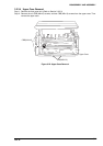
Figure 3-24. Connector and Earth Cable Removal (left side)
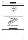
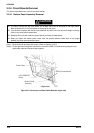
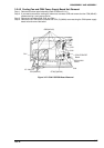
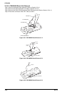
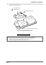
Step 5: Open the rear cover. Remove the four CBB (M3x12) screws and two CB(M3x12) screws securing
the interface cover and remove the cover.
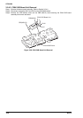
Step 6: Remove the 2 CB(M3x12) screws securing the optional interface cover and remove the cover.
CB(M3X12)
CBB(M 3X12)
Rear Cover
O ptional
In te rfa c e C o v e r
In te rfa c e C o v e r
Figure 3-25. Interface Cover Removal