


OPERATING PRINCIPLES
Rev. B
2-
5
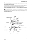
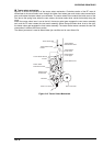
2.1.2 Carriage Mechanism
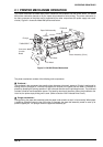
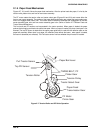
Figure 2-5 shows the carriage mechanism. The front and rear carriage guide shafts support the carriage. The
rotation of the CR motor is transmitted to the carriage timing belt through the carriage belt pulleys at the right
and left sides. The printhead is mounted on the carriage, which is attached to the carriage timing belt and
moves horizontally.
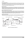
The printer does not have a carriage home position sensor; the home position is detected using disordered
pulses of the CR motor and CR encoder sensor (linear, belt-type). The head dumpers are attached to the left
and right sides of the frame. These pads are used for the absorbs the carriage hit shock for both side. The
control circuit monitors the CR motor's pulse; when it is disordered, the control circuit recognizes the carriage
home position.
The encoder belt has equally pitched slits and is mounted under the timing belt. A photo interrupter (CR
encoder) surrounds the encoder belt and converts the carriage movement into a pulse train.
T IM IN G B E L T , C R
CR Encoder Belt
SHAFT, CR, G UIDE, FRONT
CR Belt Pulley
H ead D um per (Left)
Printhead
R ibbon M ask H older
SHAFT, CR, G UIDE, REAR
CR Motor
C R Encoder Sensor
Paper W idth Sensor
Figure 2-5. Carriage Mechanism