


GENERAL DESCRIPTION
Rev. B
1-
1
9
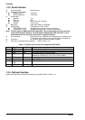
1.3 INTERFACES
The DFX-8500 is equipped with parallel interface, serial interface, and optional Type-B interface card.
This section presents the specifications for each interface type.
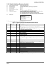
1.3.1 Parallel Interface (Forward channel)
Data transmission mode: 8-bit parallel, IEEE-1284 compatibility mode
Synchronization: /STROBE pulse
Connector type: 57-30360 (AMPHENOL) 36-pin plug or equivalent
Handshaking: BUSY and /ACK handshaking
Notes 1: BUSY signal is set high before setting either /ERROR low or PE high and held high until
all these signals return to their inactive state. BUSY signal is at a high level in the following
cases.
During data entry (see data transmission timing)
When input data buffer is full.
During /INIT signal is at a low level or during hardware initialization
During printer error (see /ERROR signal)
During test printing or during setting printing
During SelecType
When the parallel interface is not selected.
Notes 2: /ERROR signal is at a low level when the printer is in one of the following states.
Printer hardware error (fatal error)
Paper out error
Paper jam error
Cover open status
Incomplete paper change
Paper size error
Ribbon jam error
Notes 3: PE signal is at a high level during paper out error.
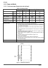
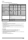
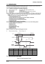
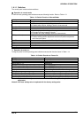
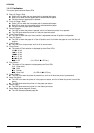
Data transmission timing: Refer to Figure 1-21.
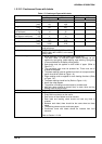
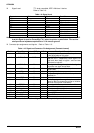
Parameter Minimum Maximum Parameter Minimum Maximum
t setup
500 ns ---
t ack
500 ns 10 us
t hold
500 ns ---
t nbusy
0 ---
t stb
500 ns ---
t next
0 ---
t ready
0 ---
tt-out*
--- 120 ns
t busy
--- 500 ns
tt-in**
--- 200 ns
t reply
--- ---
Note: * Rise and fall time of output signals
** Rise and fall time of input signals.
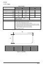
Figure 1-21. Data Transmission Timing
DATA
STROBE
BUSY
ACKNLG
t s e tu p
t ready
t busy
t s tb
t reply t ack t nbusy
t next
t hold
DATA (n)
DATA (n+1)