


DISASSEMBLY AND ASSEMBLY
Rev. B
3-3
7
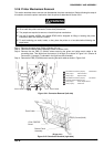
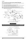
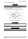
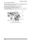
3.2.6.6 PG Sensor and PG Motor Removal
CAUTION
When you remove or install the PG sensor, be careful not to bend the PG motor encoder plate.
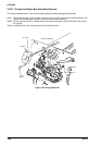
Step 1: Remove the connector junction board assembly. (Refer to Section 3.2.6.5)
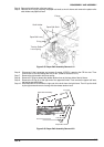
Step 2: Remove the CBS screw (3X6) securing the PG sensor unit to the left frame. Then take out the
unit to the front and remove it.
Step 3: Remove the screw securing the PG sensor to the unit, and remove the sensor.
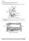
Step 4: Remove two CP (S-P1) (M3x6) screws securing the PG motor and remove the motor.
Encoder Plate
PG M otor Pinion G ear
Platen G ap Sensor
CPS(P)(M 3X6)
P G M o to r
C P (S -P 1 )(M 3 x 6 )
Figure 3-53. PG Sensor and PG Motor Removal
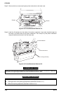
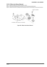
ASSEMBLING POINT
• When you install the PG motor, make sure the backlash between the PG motor and PG motor
transmission gear is between 0.05 and 0.15 mm (almost no backlash).
• When you install the PG sensor unit, align the C-cut portion of the unit with the lower shaft securing
the PG motor to the frame.
When you install the PG sensor or PG motor, perform the platen gap motor value (platen gap)
adjustment, as described in Section 4.1.7.
ADJUSTMENT REQUIRED